M5Stack Timer Camera F

M5Stack Timer Camera F
M5Stack
- Platform
- ThingsBoard
- Hardware Type
- Microcontrollers
- Connectivity
- HTTP, MQTT, WIFI, Bluetooth
- Chip
- ESP32
- Industry
- Security
- Use Case
- Smart energy, Environment Monitoring, Smart Office, Smart Retail, Smart Farming, Fleet Tracking, Health Care, Air Quality Monitoring, Waste Management, Tank Level Monitoring
Introduction
M5Stack Timer Camera F is a fisheye camera module based on ESP32-D0WDQ6-V3 with 8M PSRAM and 4M Flash on board. 3.0 megapixel camera (OV3660) with DFOV 120° and a maximum resolution of 2048x1536 photos can be captured. The camera features an ultra-low-power design, and the internal integrated RTC (BM8563) draws out the IRQ signal, which can be used for sleep and timer wake-up (sleep current down to 2μA). The built-in 270mAh battery provides more than one month of battery life with timed pictures (one per hour) enabled. The module supports Wi-Fi image transfer and USB port debugging, and the HY2.0-4P output on the bottom can be used to expand other peripherals. The on-board LED status indicator and reset button facilitate program development and debugging.
In this guide, we will learn how to create device on Thingsboard, install required libraries and tools. After this we will modify our code and upload it to the device, and check the results of our coding and check data on ThingsBoard using imported dashboard. Our device will synchronize with ThingsBoard using client and shared attributes requests functionality. Of course, we will control our device using provided functionality like shared attributes or RPC requests.
Prerequisites
To continue with this guide, we will need the following:
Create device on ThingsBoard
For simplicity, we will provide the device manually using the UI.
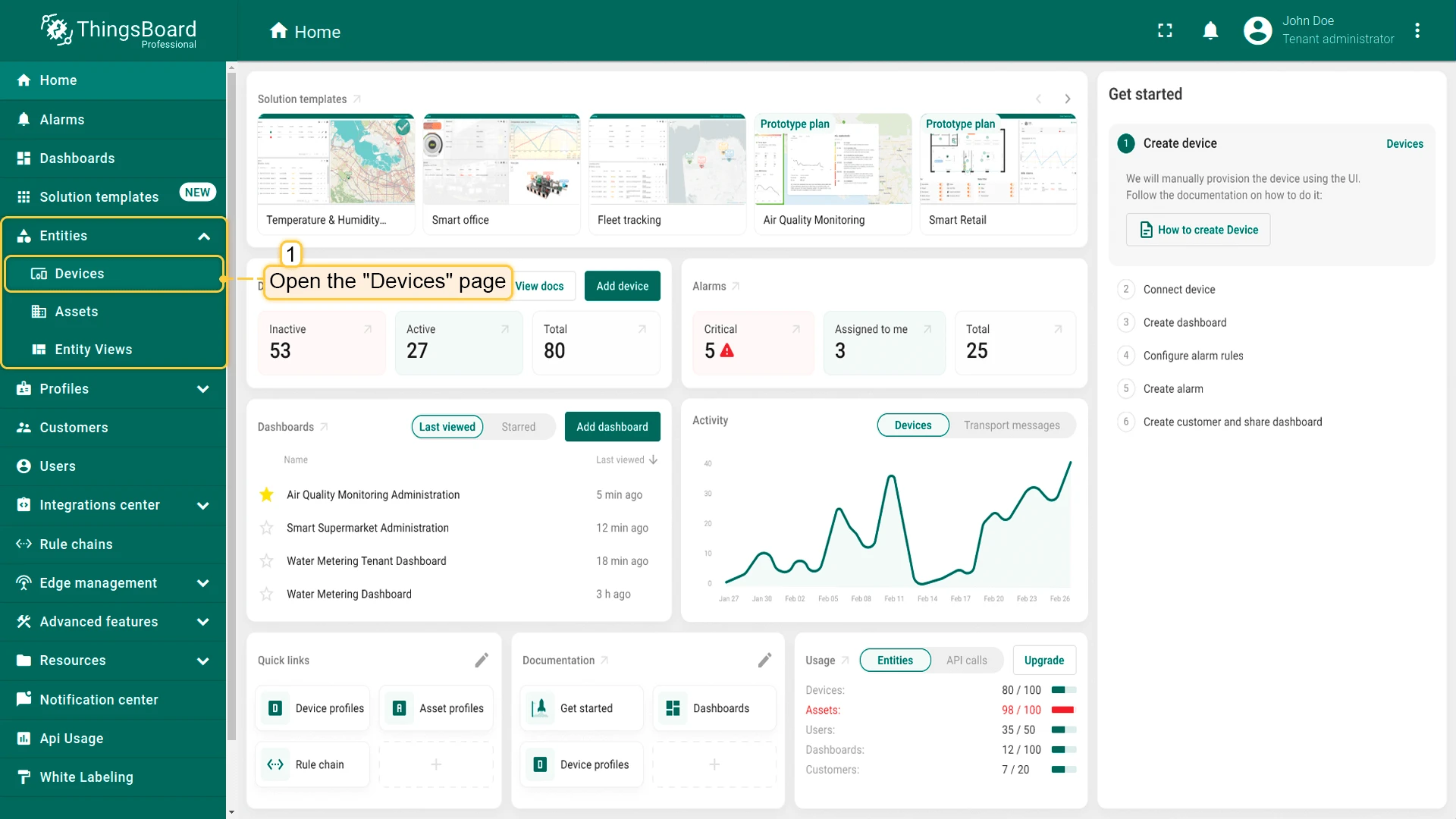
- Log in to your ThingsBoard instance and go to the Entities > Devices section.
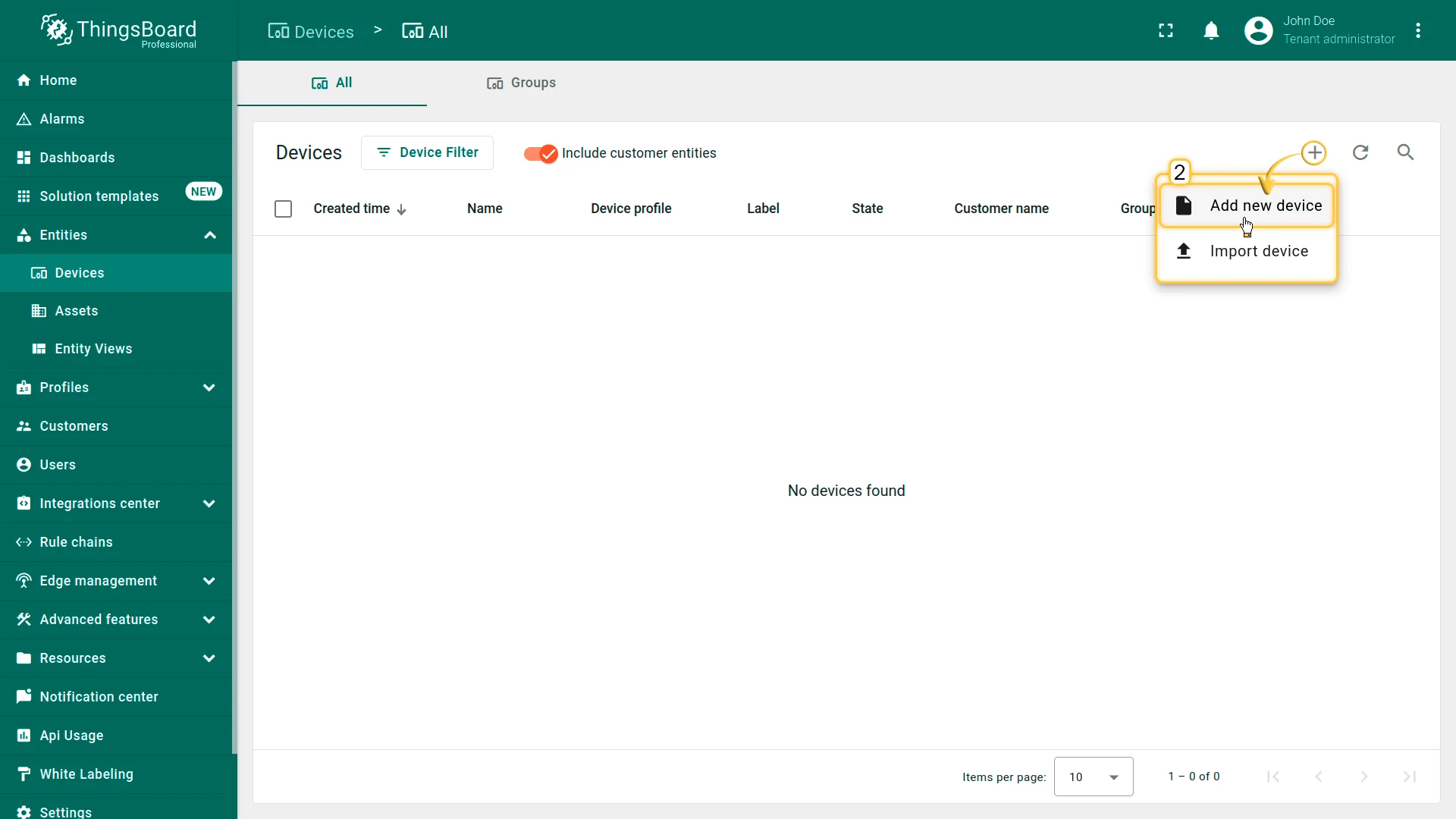
- By default, you navigate to the device group “All”. Click the “+” button in the top-right corner and select Add new device.
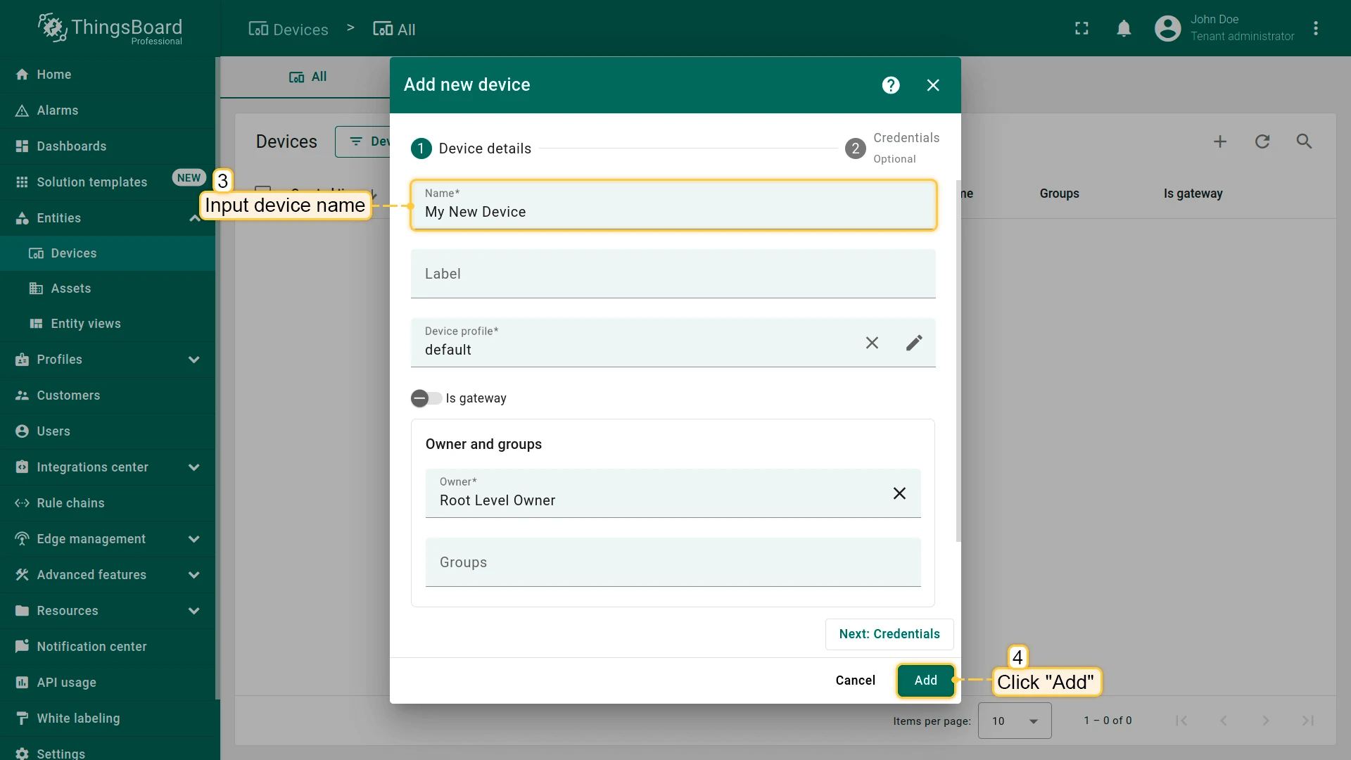
- Enter a device name, for example “My Device”. You can leave all other fields with their default values. Click Add to add the device.
- Your first device has been added.
Install required libraries and tools
Install the board for Arduino IDE:
Go to File > Preferences and add the following URL to the Additional Boards Manager URLs field.
https://m5stack.oss-cn-shenzhen.aliyuncs.com/resource/arduino/package_m5stack_index.json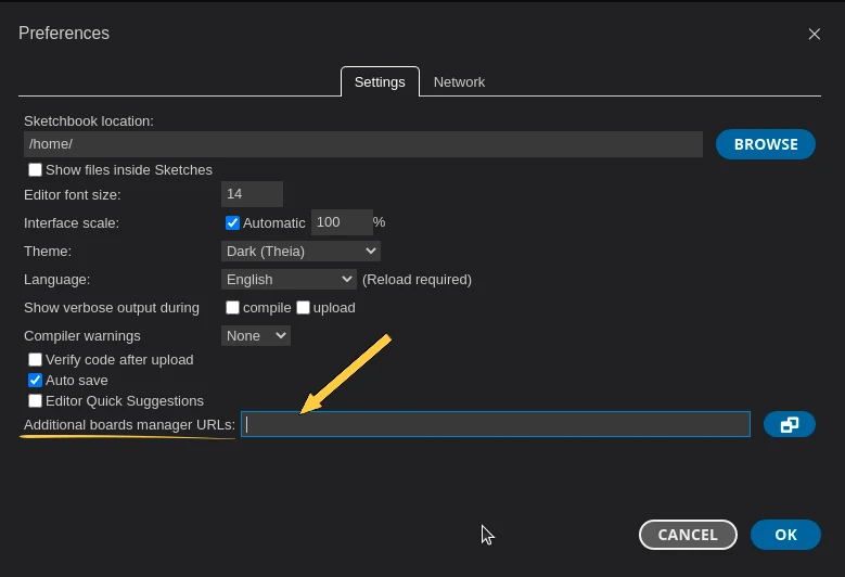
Next, go to Tools > Board > Board Manager and install the M5Stack by M5Stack Official board.
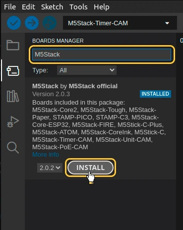
After the installation is complete, select the board by Board menu: Tools > Board > M5Stack > M5TimerCAM (Or M5Stack-Timer-CAM in older ESP-IDF versions).
Connect the device to computer using USB cable and select the port for the device: Tools > Port > /dev/ttyUSB0.
Port depends on operation system and may be different:
- for Linux it will be /dev/ttyUSBX
- for MacOS it will be usb.serialX.. or usb.modemX..
- for Windows - COMX.
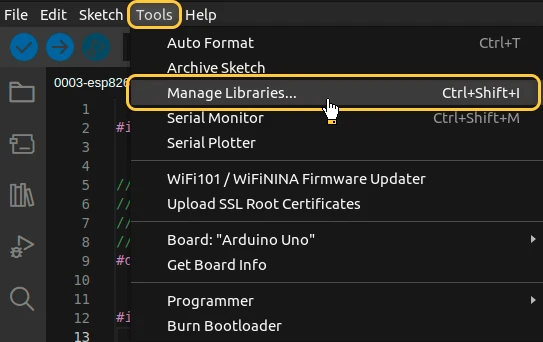
To install ThingsBoard Arduino SDK - we will need to do the following steps:
- Go to “Tools” tab and click on “Manage libraries”.
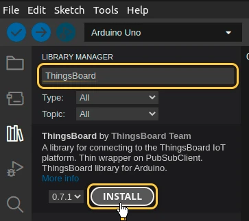
- Put “ThingsBoard” into the search box and press “INSTALL” button for the found library.
At this point, we have installed all required libraries and tools.
Connect device to ThingsBoard
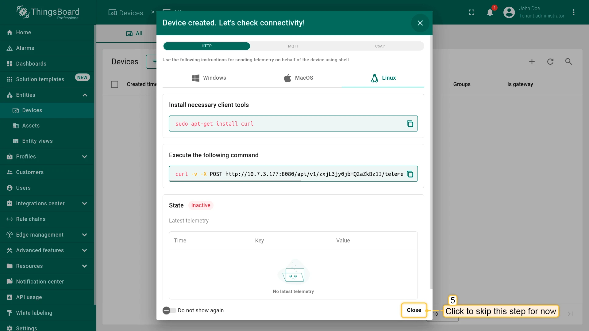
To connect your device, you’ll first need to get its credentials. While ThingsBoard supports a variety of device credentials, for this guide, we will use the default auto-generated credentials, which is an access token.
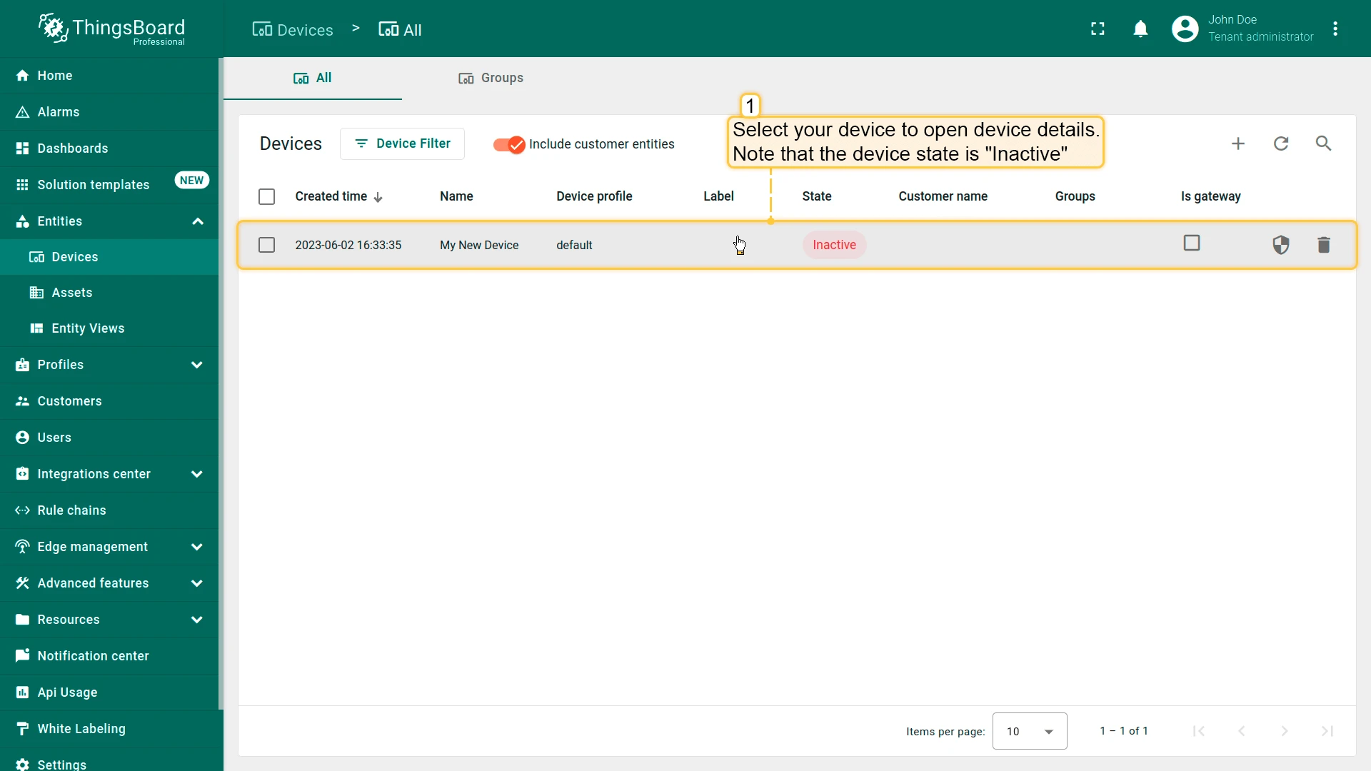
- Click on the device row in the table to open device details.
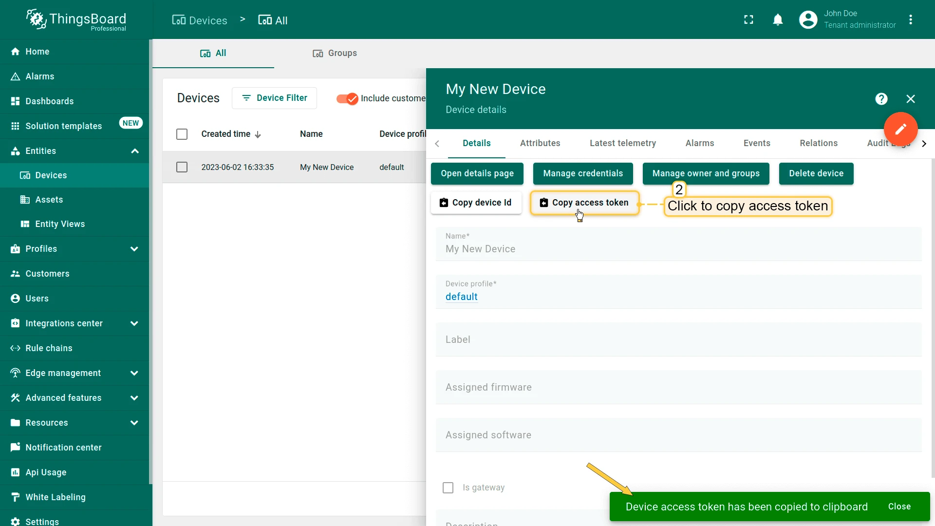
- Click “Copy access token”. The token will be copied to your clipboard. Please save it in a safe place.
Now it’s time to program the board to connect to ThingsBoard. To do this, you can use the code below. It contains all required functionality for this guide.
#include <Arduino_MQTT_Client.h>#include "esp_camera.h"#include <WiFi.h>#include "soc/soc.h"#include "soc/rtc_cntl_reg.h"
#include <Server_Side_RPC.h>#include <Attribute_Request.h>#include <Shared_Attribute_Update.h>#include <ThingsBoard.h>#include <esp_heap_caps.h>
extern "C" {#include "libb64/cencode.h"}
constexpr char WIFI_SSID[] = "YOUR_WIFI_SSID";constexpr char WIFI_PASSWORD[] = "YOUR_WIFI_PASSWORD";
// See https://thingsboard.io/docs/pe/getting-started-guides/helloworld/// to understand how to obtain an access tokenconstexpr char TOKEN[] = "YOUR_ACCESS_TOKEN";
// Thingsboard we want to establish a connection tooconstexpr char THINGSBOARD_SERVER[] = "YOUR_TB_HOST";// MQTT port used to communicate with the server, 1883 is the default unencrypted MQTT port.constexpr uint16_t THINGSBOARD_PORT = 1883U;
// Maximum size packets will ever be sent or received by the underlying MQTT client,// if the size is to small messages might not be sent or received messages will be discardedconstexpr size_t MAX_MESSAGE_SIZE = 100U * 1024;
// Baud rate for the debugging serial connection.// If the Serial output is mangled, ensure to change the monitor speed accordingly to this variableconstexpr uint32_t SERIAL_DEBUG_BAUD = 115200U;
// Maximum amount of attributs we can request or subscribe, has to be set both in the ThingsBoard template list and Attribute_Request_Callback template list// and should be the same as the amount of variables in the passed array. If it is less not all variables will be requested or subscribedconstexpr size_t MAX_ATTRIBUTES = 3U;
constexpr uint64_t REQUEST_TIMEOUT_MICROSECONDS = 5000U * 1000U;
// Definitions for camera pins#define PWDN_GPIO_NUM -1#define RESET_GPIO_NUM 15#define XCLK_GPIO_NUM 27#define SIOD_GPIO_NUM 25#define SIOC_GPIO_NUM 23#define Y9_GPIO_NUM 19#define Y8_GPIO_NUM 36#define Y7_GPIO_NUM 18#define Y6_GPIO_NUM 39#define Y5_GPIO_NUM 5#define Y4_GPIO_NUM 34#define Y3_GPIO_NUM 35#define Y2_GPIO_NUM 32#define VSYNC_GPIO_NUM 22#define HREF_GPIO_NUM 26#define PCLK_GPIO_NUM 21
// Attribute names for attribute request and attribute updates functionality
constexpr char BLINKING_INTERVAL_ATTR[] = "blinkingInterval";constexpr char LED_MODE_ATTR[] = "ledMode";constexpr char LED_STATE_ATTR[] = "ledState";constexpr char PICTURE_ATTR[] = "photo";
// Initialize underlying client, used to establish a connectionWiFiClient wifiClient;
// Initalize the Mqtt client instanceArduino_MQTT_Client mqttClient(wifiClient);
// Initialize used apisServer_Side_RPC<3U, 5U> rpc;Attribute_Request<2U, MAX_ATTRIBUTES> attr_request;Shared_Attribute_Update<3U, MAX_ATTRIBUTES> shared_update;
const std::array<IAPI_Implementation*, 3U> apis = {    &rpc,    &attr_request,    &shared_update};
// Initialize ThingsBoard instance with the maximum needed buffer size, stack size and the apis we want to useThingsBoard tb(mqttClient, MAX_MESSAGE_SIZE, Default_Max_Stack_Size, apis);
// handle led state and mode changesvolatile bool attributesChanged = false;
// LED modes: 0 - continious state, 1 - blinkingvolatile int ledMode = 0;
// Current led statevolatile bool ledState = false;
// Settings for interval in blinking modeconstexpr uint16_t BLINKING_INTERVAL_MS_MIN = 10U;constexpr uint16_t BLINKING_INTERVAL_MS_MAX = 60000U;volatile uint16_t blinkingInterval = 1000U;
uint32_t previousStateChange;
// For telemetryconstexpr int16_t telemetrySendInterval = 2000U;uint32_t previousDataSend;
// Picture bufferchar *imageBuffer;
// Flag to send a picturevolatile bool sendPicture = false;
// List of shared attributes for subscribing to their updatesconstexpr std::array<const char *, 2U> SHARED_ATTRIBUTES_LIST = {  LED_STATE_ATTR,  BLINKING_INTERVAL_ATTR};
// List of client attributes for requesting them (Using to initialize device states)constexpr std::array<const char *, 1U> CLIENT_ATTRIBUTES_LIST = {  LED_MODE_ATTR};
/// @brief Initalizes WiFi connection,// will endlessly delay until a connection has been successfully establishedvoid InitWiFi() {  Serial.println("Connecting to AP ...");  // Attempting to establish a connection to the given WiFi network  WiFi.begin(WIFI_SSID, WIFI_PASSWORD);  while (WiFi.status() != WL_CONNECTED) {    // Delay 500ms until a connection has been succesfully established    delay(500);    Serial.println(WiFi.status());    Serial.println(WL_CONNECTED);    Serial.println(".");  }  Serial.println("Connected to AP");}
/// @brief Reconnects the WiFi uses InitWiFi if the connection has been removed/// @return Returns true as soon as a connection has been established againconst bool reconnect() {  if (WiFi.status() == WL_CONNECTED) {    return true;  }
  // If we aren't establish a new connection to the given WiFi network  InitWiFi();  return true;}
bool initCamera() {  camera_config_t config;  config.ledc_channel = LEDC_CHANNEL_0;  config.ledc_timer = LEDC_TIMER_0;  config.pin_d0 = Y2_GPIO_NUM;  config.pin_d1 = Y3_GPIO_NUM;  config.pin_d2 = Y4_GPIO_NUM;  config.pin_d3 = Y5_GPIO_NUM;  config.pin_d4 = Y6_GPIO_NUM;  config.pin_d5 = Y7_GPIO_NUM;  config.pin_d6 = Y8_GPIO_NUM;  config.pin_d7 = Y9_GPIO_NUM;  config.pin_xclk = XCLK_GPIO_NUM;  config.pin_pclk = PCLK_GPIO_NUM;  config.pin_vsync = VSYNC_GPIO_NUM;  config.pin_href = HREF_GPIO_NUM;  config.pin_sscb_sda = SIOD_GPIO_NUM;  config.pin_sscb_scl = SIOC_GPIO_NUM;  config.pin_pwdn = PWDN_GPIO_NUM;  config.pin_reset = RESET_GPIO_NUM;  config.xclk_freq_hz = 20000000;  config.pixel_format = PIXFORMAT_JPEG;  config.fb_count = 1;  config.frame_size = FRAMESIZE_240X240;  config.jpeg_quality = 10;
  esp_err_t err = esp_camera_init(&config);  if (err != ESP_OK) {    Serial.printf("Camera init failed with error 0x%x", err);    return false;  }
  sensor_t *s = esp_camera_sensor_get();  // initial sensors are flipped vertically and colors are a bit saturated  s->set_vflip(s, 1);        // flip it back  s->set_brightness(s, 1);   // up the brightness just a bit  s->set_saturation(s, -2);  // lower the saturation
  return true;}
bool captureImage() {  camera_fb_t *fb = NULL;  fb = esp_camera_fb_get();  if (!fb) {    return false;  }  encode((uint8_t *)fb->buf, fb->len);  esp_camera_fb_return(fb);  return true;}
void encode(const uint8_t *data, size_t length) {  size_t size = base64_encode_expected_len(length) + 1;  base64_encodestate _state;  base64_init_encodestate(&_state);  int len = base64_encode_block((char *)&data[0], length, &imageBuffer[0], &_state);  len = base64_encode_blockend((imageBuffer + len), &_state);}
/// @brief Processes function for RPC call "setLedMode"/// RPC_Data is a JSON variant, that can be queried using operator[]/// See https://arduinojson.org/v5/api/jsonvariant/subscript/ for more details/// @param data Data containing the rpc data that was called and its current valuevoid processSetLedMode(const JsonVariantConst &data, JsonDocument &response) {  Serial.println("Received the set led state RPC method");
  // Process data  int new_mode = data;
  Serial.print("Mode to change: ");  Serial.println(new_mode);  StaticJsonDocument<1> response_doc;
  if (new_mode != 0 && new_mode != 1) {    response_doc["error"] = "Unknown mode!";    response.set(response_doc);    return;  }
  ledMode = new_mode;
  attributesChanged = true;
  // Returning current mode  response_doc["newMode"] = (int)ledMode;  response.set(response_doc);}
/// @brief Processes function for RPC call "setLedMode"/// RPC_Data is a JSON variant, that can be queried using operator[]/// See https://arduinojson.org/v5/api/jsonvariant/subscript/ for more details/// @param data Data containing the rpc data that was called and its current valuevoid processTakePicture(const JsonVariantConst &data, JsonDocument &response) {  Serial.println("Received the take picture RPC method");  StaticJsonDocument<1> response_doc;
  if (!captureImage()) {    response_doc["error"] = "Cannot take a picture!";    response.set(response_doc);    return;  }
  sendPicture = true;
  // Returning picture size  response_doc["size"] = strlen(imageBuffer);  response.set(response_doc);}
// Optional, keep subscribed shared attributes empty instead,// and the callback will be called for every shared attribute changed on the device,// instead of only the one that were entered insteadconst std::array<RPC_Callback, 2U> callbacks = {  RPC_Callback{ "setLedMode", processSetLedMode },  RPC_Callback{ "takePicture", processTakePicture }};
/// @brief Update callback that will be called as soon as one of the provided shared attributes changes value,/// if none are provided we subscribe to any shared attribute change instead/// @param data Data containing the shared attributes that were changed and their current valuevoid processSharedAttributes(const JsonObjectConst &data) {  for (auto it = data.begin(); it != data.end(); ++it) {    if (strcmp(it->key().c_str(), BLINKING_INTERVAL_ATTR) == 0) {      const uint16_t new_interval = it->value().as<uint16_t>();      if (new_interval >= BLINKING_INTERVAL_MS_MIN && new_interval <= BLINKING_INTERVAL_MS_MAX) {        blinkingInterval = new_interval;        Serial.print("Updated blinking interval to: ");        Serial.println(new_interval);      }    } else if (strcmp(it->key().c_str(), LED_STATE_ATTR) == 0) {      ledState = it->value().as<bool>();      digitalWrite(LED_BUILTIN, ledState ? HIGH : LOW);      Serial.print("Updated state to: ");      Serial.println(ledState);    }  }  attributesChanged = true;}
void processClientAttributes(const JsonObjectConst &data) {  for (auto it = data.begin(); it != data.end(); ++it) {    if (strcmp(it->key().c_str(), LED_MODE_ATTR) == 0) {      const uint16_t new_mode = it->value().as<uint16_t>();      ledMode = new_mode;    }  }}
// Attribute request did not receive a response in the expected amount of microsecondsvoid requestTimedOut() {  Serial.printf("Attribute request timed out did not receive a response in (%llu) microseconds. Ensure client is connected to the MQTT broker and that the keys actually exist on the target device\n", REQUEST_TIMEOUT_MICROSECONDS);}
const Shared_Attribute_Callback<MAX_ATTRIBUTES> attributes_callback(&processSharedAttributes, SHARED_ATTRIBUTES_LIST.cbegin(), SHARED_ATTRIBUTES_LIST.cend());const Attribute_Request_Callback<MAX_ATTRIBUTES> attribute_shared_request_callback(&processSharedAttributes, REQUEST_TIMEOUT_MICROSECONDS, &requestTimedOut, SHARED_ATTRIBUTES_LIST);const Attribute_Request_Callback<MAX_ATTRIBUTES> attribute_client_request_callback(&processClientAttributes, REQUEST_TIMEOUT_MICROSECONDS, &requestTimedOut, CLIENT_ATTRIBUTES_LIST);
void setup() {  WRITE_PERI_REG(RTC_CNTL_BROWN_OUT_REG, 0);  ledcAttachPin(4, 4);  ledcSetup(4, 5000, 8);
  imageBuffer = (char *)ps_malloc(50U * 1024);  Serial.begin(SERIAL_DEBUG_BAUD);  Serial.println("Camera initialization...");  if (!initCamera()) {    Serial.println("Camera initialization failed!");    ESP.restart();  }
  pinMode(LED_BUILTIN, OUTPUT);  delay(1000);  InitWiFi();  tb.connect(THINGSBOARD_SERVER, TOKEN, THINGSBOARD_PORT);  rpc.RPC_Subscribe(callbacks.cbegin(), callbacks.cend());  shared_update.Shared_Attributes_Subscribe(attributes_callback);  attr_request.Shared_Attributes_Request(attribute_shared_request_callback);  attr_request.Client_Attributes_Request(attribute_client_request_callback);}
void loop() {  delay(10);
  if (!reconnect()) {    return;  }
  if (!tb.connected()) {      // Connect to the ThingsBoard      Serial.print("Connecting to: ");      Serial.print(THINGSBOARD_SERVER);      Serial.print(" with token ");      Serial.println(TOKEN);    if (!tb.connect(THINGSBOARD_SERVER, TOKEN, THINGSBOARD_PORT)) {      Serial.println("Failed to connect");      return;    }  Serial.println("Connection to server successful");  // Sending a MAC address as an attribute  tb.sendAttributeData("macAddress", WiFi.macAddress().c_str());
  Serial.println("Subscribing for RPC...");  // Perform a subscription. All consequent data processing will happen in  // processSetLedState() and processSetLedMode() functions,  // as denoted by callbacks array.  if (!rpc.RPC_Subscribe(callbacks.cbegin(), callbacks.cend())) {    Serial.println("Failed to subscribe for RPC");    return;  }
  if (!shared_update.Shared_Attributes_Subscribe(attributes_callback)) {    Serial.println("Failed to subscribe for shared attribute updates");    return;  }
  Serial.println("Subscribe done");
  // Request current states of shared attributes  if (!attr_request.Shared_Attributes_Request(attribute_shared_request_callback)) {    Serial.println("Failed to request for shared attributes");    return;  }
  // Request current states of client attributes  if (!attr_request.Client_Attributes_Request(attribute_client_request_callback)) {    Serial.println("Failed to request for client attributes");    return;  }  }
  if (sendPicture) {    tb.sendTelemetryData(PICTURE_ATTR, imageBuffer);    sendPicture = false;  }
  if (attributesChanged) {    attributesChanged = false;    if (ledMode == 0) {      previousStateChange = millis();    }    tb.sendTelemetryData(LED_MODE_ATTR, ledMode);    tb.sendTelemetryData(LED_STATE_ATTR, ledState);    tb.sendAttributeData(LED_MODE_ATTR, ledMode);    tb.sendAttributeData(LED_STATE_ATTR, ledState);  }
  if (ledMode == 1 && millis() - previousStateChange > blinkingInterval) {    previousStateChange = millis();    ledState = !ledState;    digitalWrite(LED_BUILTIN, ledState);    tb.sendTelemetryData(LED_STATE_ATTR, ledState);    tb.sendAttributeData(LED_STATE_ATTR, ledState);    if (LED_BUILTIN == 99) {      Serial.print("LED state changed to: ");      Serial.println(ledState);    }  }
  // Sending telemetry every telemetrySendInterval time  if (millis() - previousDataSend > telemetrySendInterval) {    previousDataSend = millis();    tb.sendTelemetryData("temperature", random(10, 20));    tb.sendAttributeData("rssi", WiFi.RSSI());    tb.sendAttributeData("channel", WiFi.channel());    tb.sendAttributeData("ssid", WIFI_SSID);    tb.sendAttributeData("localIp", WiFi.localIP().toString().c_str());  }
tb.loop();}Necessary variables for connection:
| Variable name | Default value | Description |
|---|---|---|
| WIFI_SSID | YOUR_WIFI_SSID | Your WiFi network name. |
| WIFI_PASSWORD | YOUR_WIFI_PASSWORD | Your WiFi network password. |
| TOKEN | YOUR_DEVICE_ACCESS_TOKEN | Access token from device. Obtaining process described in #connect-device-to-thingsboard |
| THINGSBOARD_SERVER | YOUR_TB_HOST | Your ThingsBoard host or ip address. |
| THINGSBOARD_PORT | 1883U | ThingsBoard server MQTT port. Can be default for this guide. |
| MAX_MESSAGE_SIZE | 100U*1024 | Maximal size of MQTT messages. Should be more than picture size + ~1024 or more. |
| SERIAL_DEBUG_BAUD | 1883U | Baud rate for serial port. Can be default for this guide. |
...
constexpr char WIFI_SSID[] = "YOUR_WIFI_SSID";constexpr char WIFI_PASSWORD[] = "YOUR_WIFI_PASSWORD";
constexpr char TOKEN[] = "YOUR_ACCESS_TOKEN";
constexpr char THINGSBOARD_SERVER[] = "YOUR_TB_HOST";constexpr uint16_t THINGSBOARD_PORT = 1883U;
constexpr uint32_t MAX_MESSAGE_SIZE = 100U * 1024;constexpr uint32_t SERIAL_DEBUG_BAUD = 115200U;
...
Send data part (By default the example sends random value for temperature key and some WiFi information):
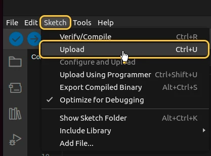
... tb.sendTelemetryData("temperature", random(10, 20)); tb.sendAttributeData("rssi", WiFi.RSSI()); tb.sendAttributeData("bssid", WiFi.BSSIDstr().c_str()); tb.sendAttributeData("localIp", WiFi.localIP().toString().c_str()); tb.sendAttributeData("ssid", WiFi.SSID().c_str()); tb.sendAttributeData("channel", WiFi.channel());...Then upload the code to the device by pressing Upload button or keyboard combination Ctrl+U.
Check data on ThingsBoard
ThingsBoard provides the ability to create and customize interactive visualizations (dashboards) for monitoring and managing data and devices. Through ThingsBoard dashboards, you can efficiently manage and monitor your IoT devices and data. So, we will create the dashboard, for our device.
To add the dashboard to ThingsBoard, we need to import it. To import a dashboard, follow these steps:
- First download the Check and control device data dashboard file.
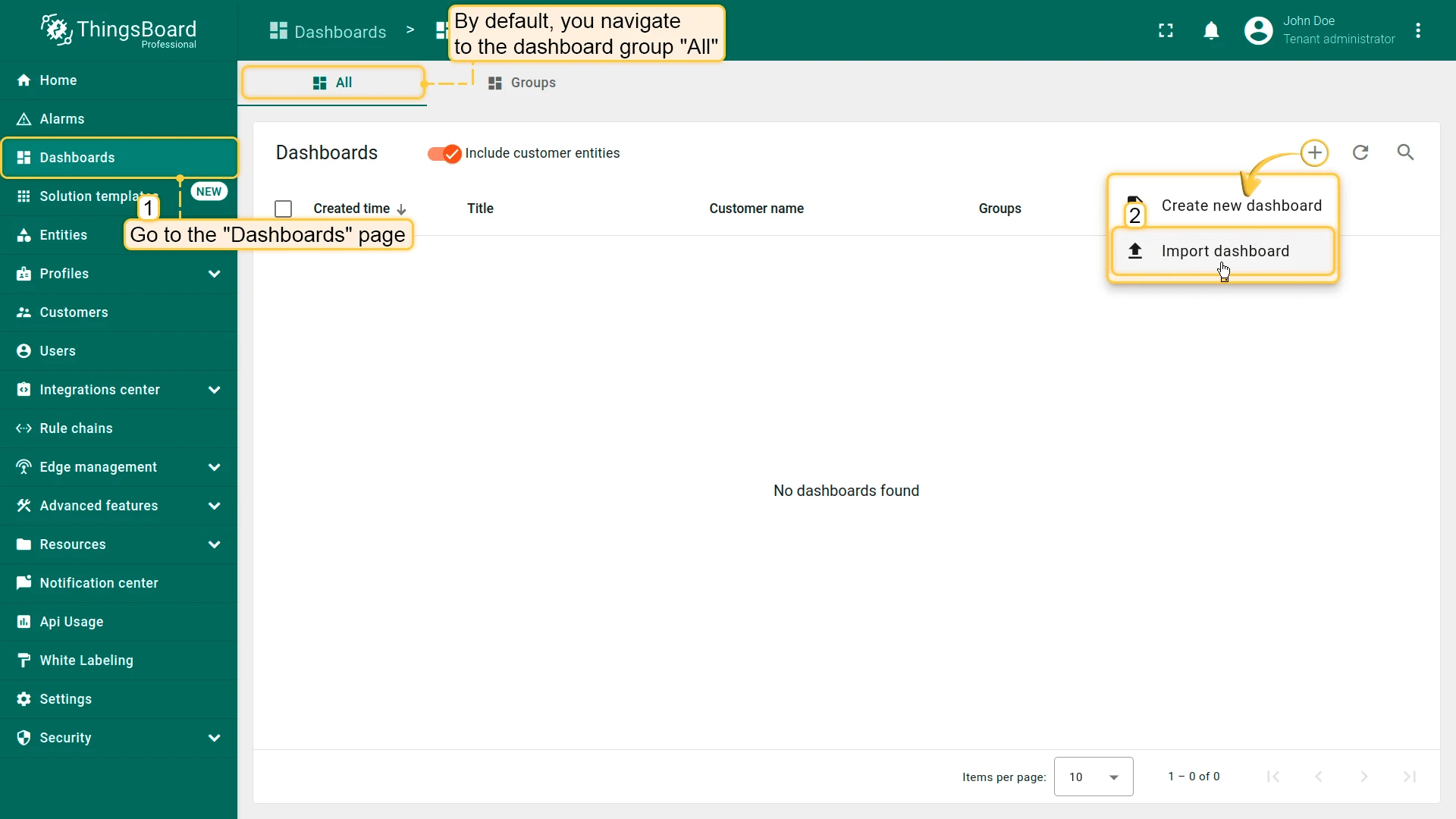
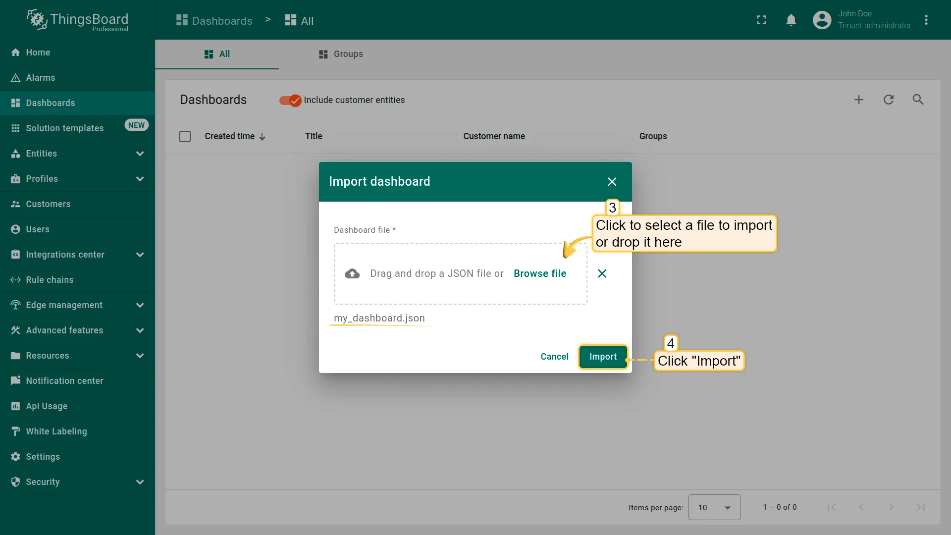
- Navigate to the “Dashboards” page. By default, you navigate to the dashboard group “All”. Click on the ”+” icon in the top right corner. Select “Import dashboard”.
- In the dashboard import window, upload the JSON file and click “Import” button.
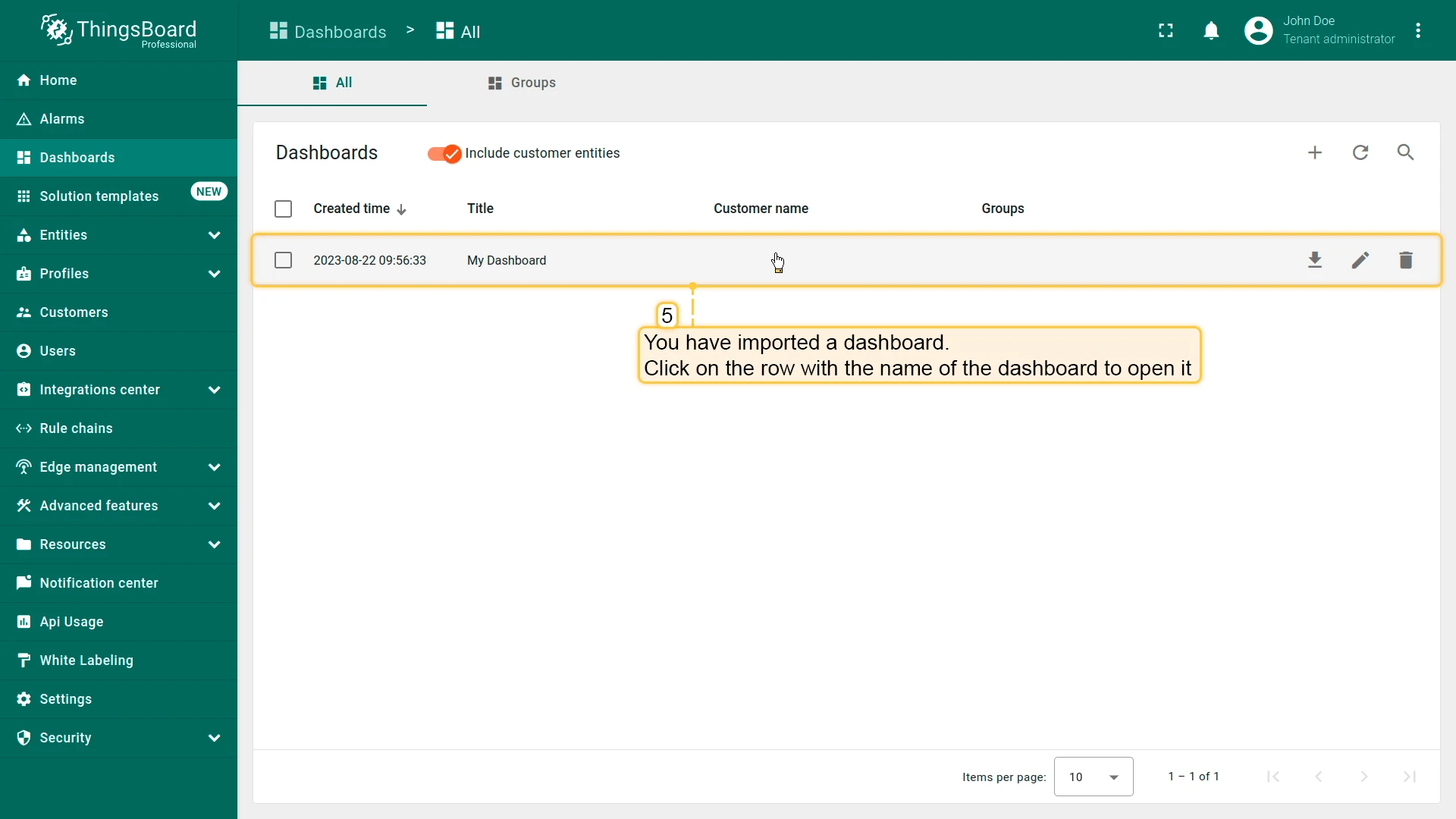
- Dashboard has been imported.
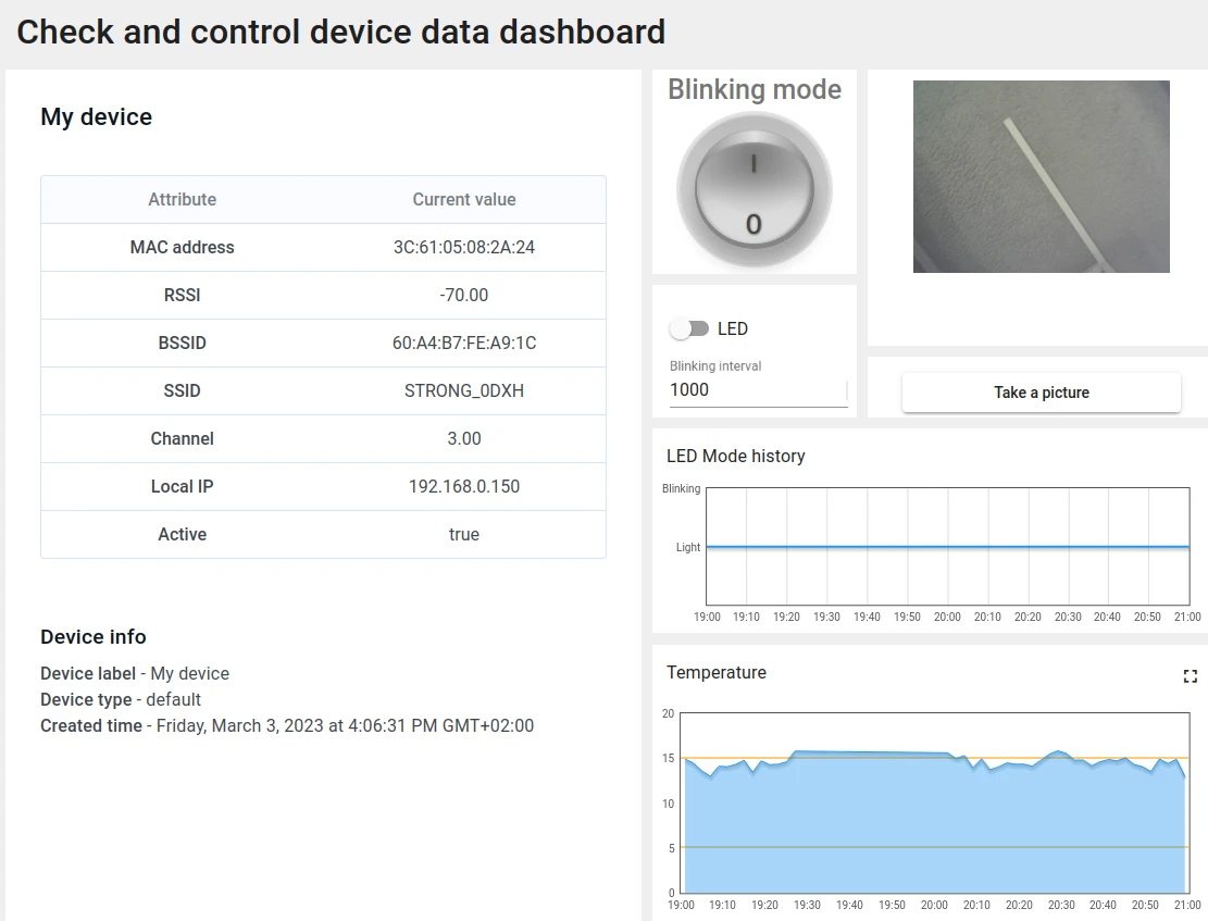
The Check and control device data dashboard structure:
- To check the data from our device we need to open the imported dashboard by clicking on it in the table.
- The view of checking data and controlling our device dashboard.
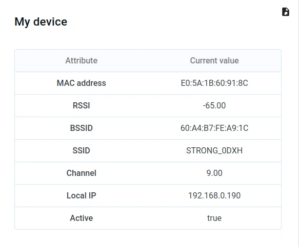
- Received attributes from device.
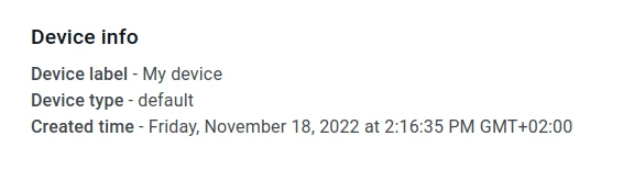
- Device information from the ThingsBoard server.
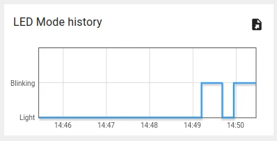
- Widget to see the history of LED mode changes.
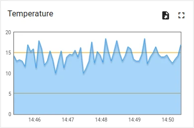
- Widget to see the history of our emulated temperature.
Synchronize device state using client and shared attribute requests
In order to get the state of the device from ThingsBoard during booting we have functionality to do this in the code.
Below are the relevant parts of the code example:
- Connecting modules to use API functionality:
...#include <AttributeRequest.h>...Attribute_Request<2U, MAX_ATTRIBUTES> attr_request;...const std::array<IAPI_Implementation*, ...> apis = { ... &attr_request, ...};...We need to define what API we will use in our code.
- Attribute callbacks:
...void processSharedAttributes(const JsonObjectConst &data) {  for (auto it = data.begin(); it != data.end(); ++it) {    if (strcmp(it->key().c_str(), BLINKING_INTERVAL_ATTR) == 0) {      const uint16_t new_interval = it->value().as<uint16_t>();      if (new_interval >= BLINKING_INTERVAL_MS_MIN && new_interval <= BLINKING_INTERVAL_MS_MAX) {        blinkingInterval = new_interval;        Serial.print("Updated blinking interval to: ");        Serial.println(new_interval);      }    } else if(strcmp(it->key().c_str(), LED_STATE_ATTR) == 0) {      ledState = it->value().as<bool>();      digitalWrite(LED_BUILTIN, ledState ? HIGH : LOW);      Serial.print("Updated state to: ");      Serial.println(ledState);    }  }  attributesChanged = true;}
void processClientAttributes(const JsonObjectConst &data) {  for (auto it = data.begin(); it != data.end(); ++it) {    if (strcmp(it->key().c_str(), LED_MODE_ATTR) == 0) {      const uint16_t new_mode = it->value().as<uint16_t>();      ledMode = new_mode;    }  }}...// Attribute request did not receive a response in the expected amount of microsecondsvoid requestTimedOut() {  Serial.printf("Attribute request timed out did not receive a response in (%llu) microseconds. Ensure client is connected to the MQTT broker and that the keys actually exist on the target device\n", REQUEST_TIMEOUT_MICROSECONDS);}...const Attribute_Request_Callback<MAX_ATTRIBUTES> attribute_shared_request_callback(&processSharedAttributes, REQUEST_TIMEOUT_MICROSECONDS, &requestTimedOut, SHARED_ATTRIBUTES_LIST);const Attribute_Request_Callback<MAX_ATTRIBUTES> attribute_client_request_callback(&processClientAttributes, REQUEST_TIMEOUT_MICROSECONDS, &requestTimedOut, CLIENT_ATTRIBUTES_LIST);...
We have three callbacks:
- Shared Attributes Callback: This callback is specific to shared attributes. Its primary function is to receive a response containing the blinking interval, which determines the appropriate blinking period.;
- Client Attributes Callback: This callback is specific to client attributes. It receives information regarding the mode and state of the LED. Once this data is received, the system saves and sets these parameters.
- Request Timeout Callback: This callback is triggered when the request for attribute data times out. It is used to handle the timeout event.
This functionality allows us to keep the actual state after rebooting.
- Attribute requests:
...    // Request current states of shared attributes    if (!attr_request.Shared_Attributes_Request(attribute_shared_request_callback)) {      Serial.println("Failed to request for shared attributes");      return;    }
    // Request current states of client attributes    if (!attr_request.Client_Attributes_Request(attribute_client_request_callback)) {      Serial.println("Failed to request for client attributes");      return;    }...
In order for our callbacks to receive the data, we have to send a request to ThingsBoard.
Control device using shared attributes
Also we can change the period of the blinking using shared attribute update functionality.
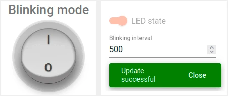
- To change period of the blinking we just need to change the value on our dashboard.
- After applying by pressing check mark you will see a confirmation message.
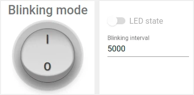
In order to change state when blinking is disabled - we can use the switch in the same widget:
- It can be done only when the blinking mode is disabled.
To reach this, we have a variable “blinkingInterval” used in the following parts of the code:
- Connecting modules to use API functionality:
...#include <AttributeRequest.h>...Attribute_Request<2U, MAX_ATTRIBUTES> attr_request;...const std::array<IAPI_Implementation*, ...> apis = { ... &shared_update ...};...To use attribute requests functionality we need to include related module and define it as a part of used API.
- Callback for shared attributes update:
...
void processSharedAttributes(const JsonObjectConst &data) {  for (auto it = data.begin(); it != data.end(); ++it) {    if (strcmp(it->key().c_str(), BLINKING_INTERVAL_ATTR) == 0) {      const uint16_t new_interval = it->value().as<uint16_t>();      if (new_interval >= BLINKING_INTERVAL_MS_MIN && new_interval <= BLINKING_INTERVAL_MS_MAX) {        blinkingInterval = new_interval;        Serial.print("Updated blinking interval to: ");        Serial.println(new_interval);      }    } else if(strcmp(it->key().c_str(), LED_STATE_ATTR) == 0) {      ledState = it->value().as<bool>();      digitalWrite(LED_BUILTIN, ledState ? HIGH : LOW);      Serial.print("Updated state to: ");      Serial.println(ledState);    }  }  attributesChanged = true;}
...// Attribute request did not receive a response in the expected amount of microsecondsvoid requestTimedOut() { Serial.printf("Attribute request timed out did not receive a response in (%llu) microseconds. Ensure client is connected to the MQTT broker and that the keys actually exist on the target device\n", REQUEST_TIMEOUT_MICROSECONDS);}...const Attribute_Request_Callback<MAX_ATTRIBUTES> attribute_shared_request_callback(&processSharedAttributes, REQUEST_TIMEOUT_MICROSECONDS, &requestTimedOut, SHARED_ATTRIBUTES_LIST);...- Subscribing for shared attributes update:
... if (!shared_update.Shared_Attributes_Request(attribute_shared_request_callback)) { Serial.println("Failed to request for shared attributes"); return; }...- Part of code to blink:
...
  if (ledMode == 1 && millis() - previousStateChange > blinkingInterval) {    previousStateChange = millis();    ledState = !ledState;    digitalWrite(LED_BUILTIN, ledState);    tb.sendTelemetryData(LED_STATE_ATTR, ledState);    tb.sendAttributeData(LED_STATE_ATTR, ledState);    if (LED_BUILTIN == 99) {      Serial.print("LED state changed to: ");      Serial.println(ledState);    }  }...
You can change the logic to reach your goals and add processing for your attributes.
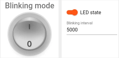
Control device using RPC
You can manually change state of the LED and change mode between continuous lightning and blinking. To do this, you can use the following parts of our dashboard:
- Change LED state using switch widget to continuous lightning.
- Change LED state using round switch widget to blinking mode.
Please note that you can change the LED state only if blinking mode is disabled.
In the code example we have functionality to handle RPC commands. To get ability to control the device we have used the following parts of the code:
- Connecting modules to use API functionality:
...#include <Server_Side_RPC.h>...Server_Side_RPC<..., ...> rpc;...
const std::array<IAPI_Implementation*, ...> apis = {    ...    &rpc,    ...    }...
To use RPC we need to include related module and define it as a part of used API.
- Callback for RPC requests:
...
void processSetLedMode(const JsonVariantConst &data, JsonDocument &response) {  Serial.println("Received the set led state RPC method");
  // Process data  int new_mode = data;
  Serial.print("Mode to change: ");  Serial.println(new_mode);  StaticJsonDocument<1> response_doc;
  if (new_mode != 0 && new_mode != 1) {    response_doc["error"] = "Unknown mode!";    response.set(response_doc);    return;  }
  ledMode = new_mode;
  attributesChanged = true;
  response_doc["newMode"] = (int)ledMode;  // Returning current mode  response.set(response_doc);}
...
const std::array<RPC_Callback, 2U> callbacks = {  RPC_Callback{ "setLedMode", processSetLedMode },  RPC_Callback{ "takePicture", processTakePicture }};
...- Subscribing for RPC requests:
... if (!rpc.RPC_Subscribe(callbacks.cbegin(), callbacks.cend())) { Serial.println("Failed to subscribe for RPC"); return; }...Such as the board has included camera we can take a picture and see it on the dashboard.
- You can take a picture from camera module, by pressing the button on ThingsBoard dashboard.
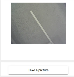
To take a picture we send “takePicture” RPC to the device.
The following part of the code takes a picture.
...
bool captureImage() {  camera_fb_t *fb = NULL;  fb = esp_camera_fb_get();  if (!fb) {    return false;  }  encode((uint8_t *)fb->buf, fb->len);  esp_camera_fb_return(fb);  return true;}...
We are unable to send a raw bytes array of the photo in JSON, so we are also encoding bytes to Base64:
...void encode(const uint8_t *data, size_t length) { size_t size = base64_encode_expected_len(length) + 1; base64_encodestate _state; base64_init_encodestate(&_state); int len = base64_encode_block((char *)&data[0], length, &imageBuffer[0], &_state); len = base64_encode_blockend((imageBuffer + len), &_state);}...Our encoded picture will be sent in the main loop:
...if (sendPicture) {tb.sendTelemetryData(PICTURE_ATTR, imageBuffer);sendPicture = false;}...You can change the code to reach your goals and add processing for your RPC commands.
Conclusion
Now you can easily connect your M5Stack Timer Camera F and start sending data to ThingsBoard.
To go further, explore the ThingsBoard documentation to learn more about key features, such as creating dashboards to visualize your telemetry, or setting up alarm rules to monitor device behavior in real time.