DRN 500
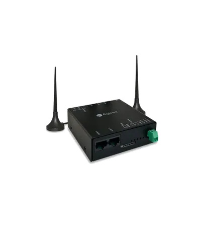
DRN 500
Digicom
- Platform
- ThingsBoard
- Hardware Type
- Gateways
- Connectivity
- LTE, Wi-Fi, Ethernet, Modbus, MQTT
- Industry
- Energy Management, Smart Cities, Industrial Manufacturing
- Use Case
- Smart Energy, Smart Metering, Environment Monitoring
Introduction
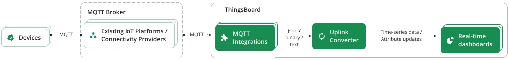
The Digicom DRN 500 is a multifunction 4G router with built-in Modbus master and MQTT client. It reads registers from serial Modbus devices (like energy meters), publishes the data to an external MQTT broker, and ThingsBoard subscribes to that broker through an MQTT Integration.
This guide covers connecting a DRN 500 to ThingsBoard via an external MQTT broker, reading energy meter telemetry (voltage, current, frequency, power), and visualizing it on a dashboard.
Prerequisites
- Digicom DRN 500 with firmware 1.10 or newer
- Energy meter connected via Modbus serial
- External MQTT broker (publicly reachable)
- ThingsBoard PE instance: use ThingsBoard Cloud or install a local PE server
ThingsBoard setup
Create the MQTT integration
The MQTT Integration connects to an external broker, subscribes to data streams, and converts payloads to ThingsBoard telemetry format. Use it when devices publish to an external broker rather than directly to ThingsBoard.
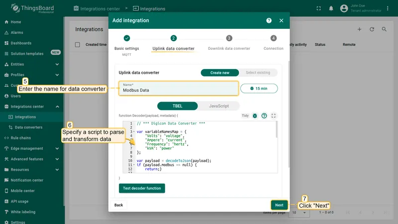
// *** Digicom Data Converter ***
var variableNamesMap = {  "Volts": "voltage",  "Ampere": "current",  "Frequency": "hertz",  "kVA": "power"};
var payload = decodeToJson(payload);if (payload.modbus == null) {  return;}
var telemetry = [];var telemetries = payload.modbus.data[0].samples;foreach(sample: telemetries) {  var values = {};  var varName = variableNamesMap[sample.reg];  if (varName != null) {    values[varName] = sample.value;    telemetry.push({      ts: Long.parseLong(sample        .timestamp) * 1000,      values: values    });  }}
var result = {  deviceName: payload.serialnum,  deviceType: payload.type,  attributes: {    model: payload.model,    integrationName: metadata['integrationName'],  },  telemetry: telemetry};
/** Helper functions 'decodeToString' and 'decodeToJson' are already built-in **/
return result;-
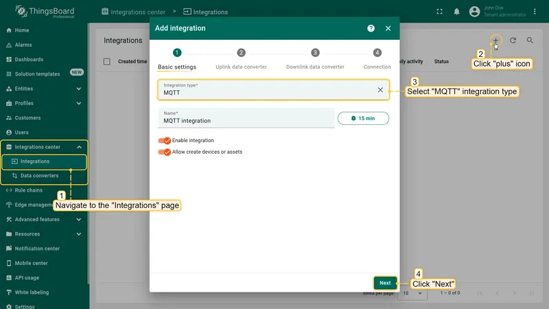
Go to Integrations center ⇾ Integrations and click + Add integration.
-
Select MQTT as the integration type and click Next.
-
In the Uplink data converter step, enter a name, select TBEL, clear the default content, paste the decoder above, and click Next.
-
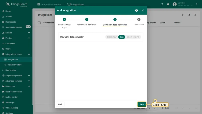
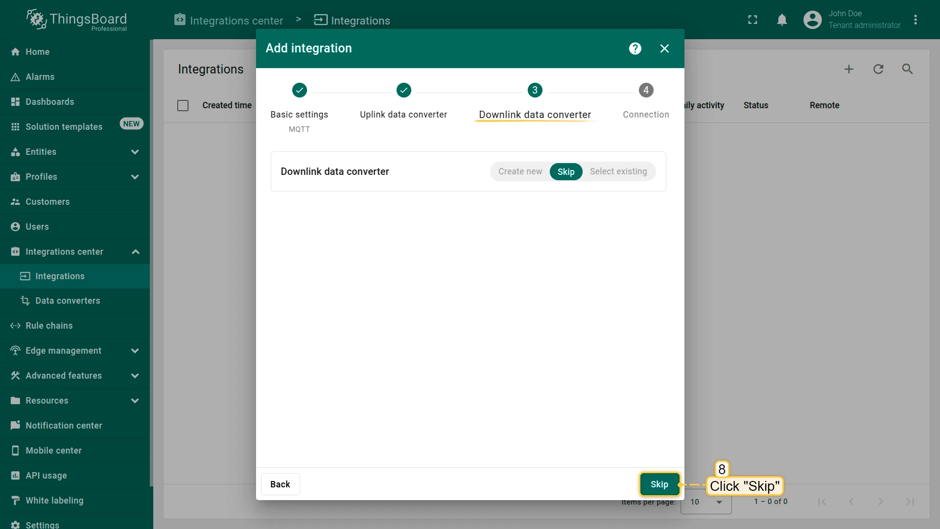
Click Skip in the Downlink data converter step.
-
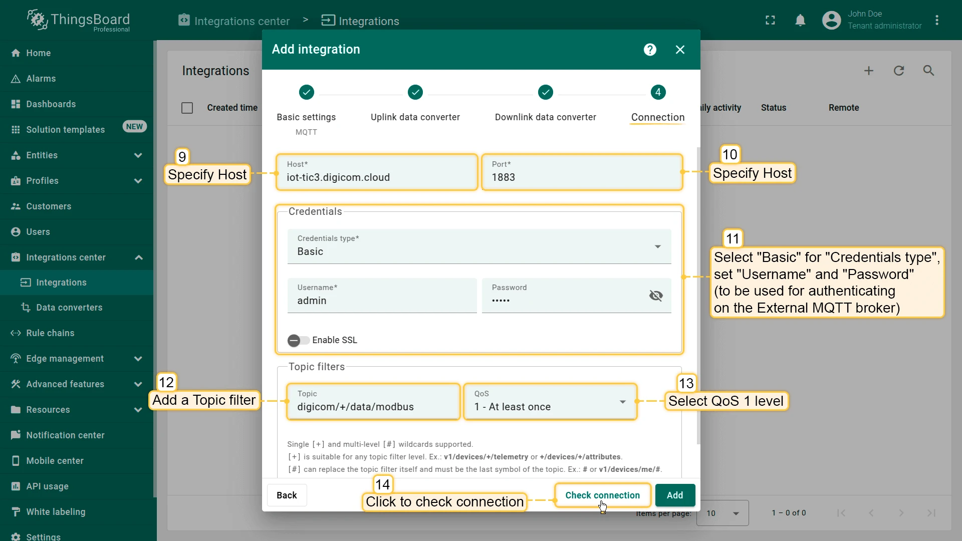
Fill in the Connection tab:
- Set Host and Port of the external MQTT broker (e.g.
iot-tic3.digicom.cloudand1883). - Set Credentials type to Basic and enter Username and Password.
- Add topic filter:
digicom/+/data/modbus, QoS 1.
Click Check connection to verify, then click Add.
- Set Host and Port of the external MQTT broker (e.g.


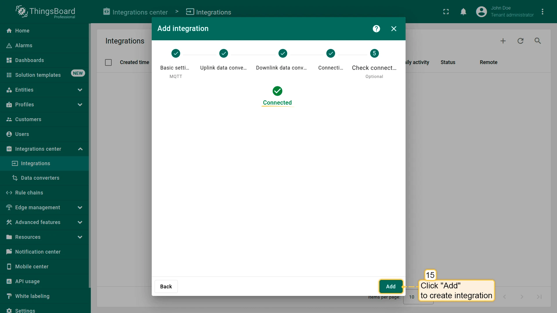
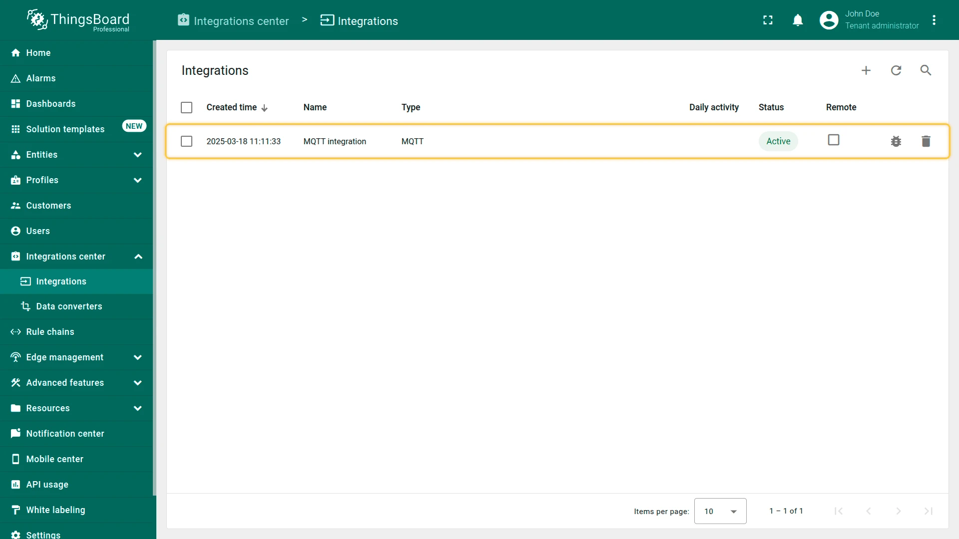
Once created, the integration status shows Active if the broker connection succeeds. If it remains Inactive, check the broker address, port, and credentials.
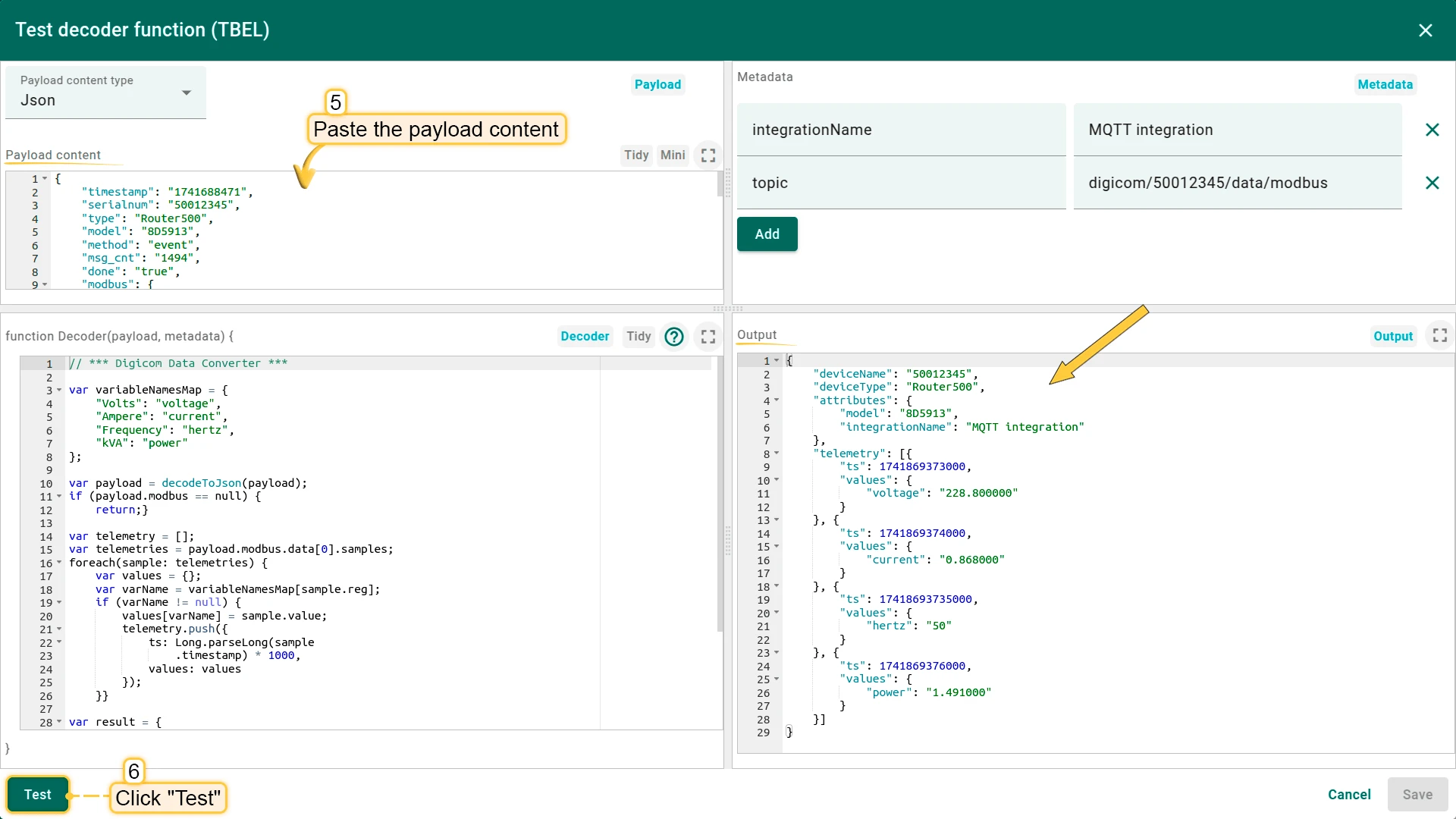
Test the data converter
You can test the decoder before real data arrives. Use the sample payload below.
{ "timestamp": "1741688471", "serialnum": "50012345", "type": "Router500", "model": "8D5913", "method": "event", "msg_cnt": "1494", "done": "true", "modbus": { "data": [{ "device": "Energy_Meter", "event": "read", "samples": [{ "timestamp": "1741869373", "reg": "Volts", "unit": "V", "value": "228.800000", "deferred": "false" }, { "timestamp": "1741869374", "reg": "Ampere", "unit": "A", "value": "0.868000", "deferred": "false" }, { "timestamp": "17418693735", "reg": "Frequency", "unit": "Hz", "value": "50", "deferred": "false" }, { "timestamp": "1741869376", "reg": "kVA", "unit": "kVA", "value": "1.491000", "deferred": "false" }] }] }}-
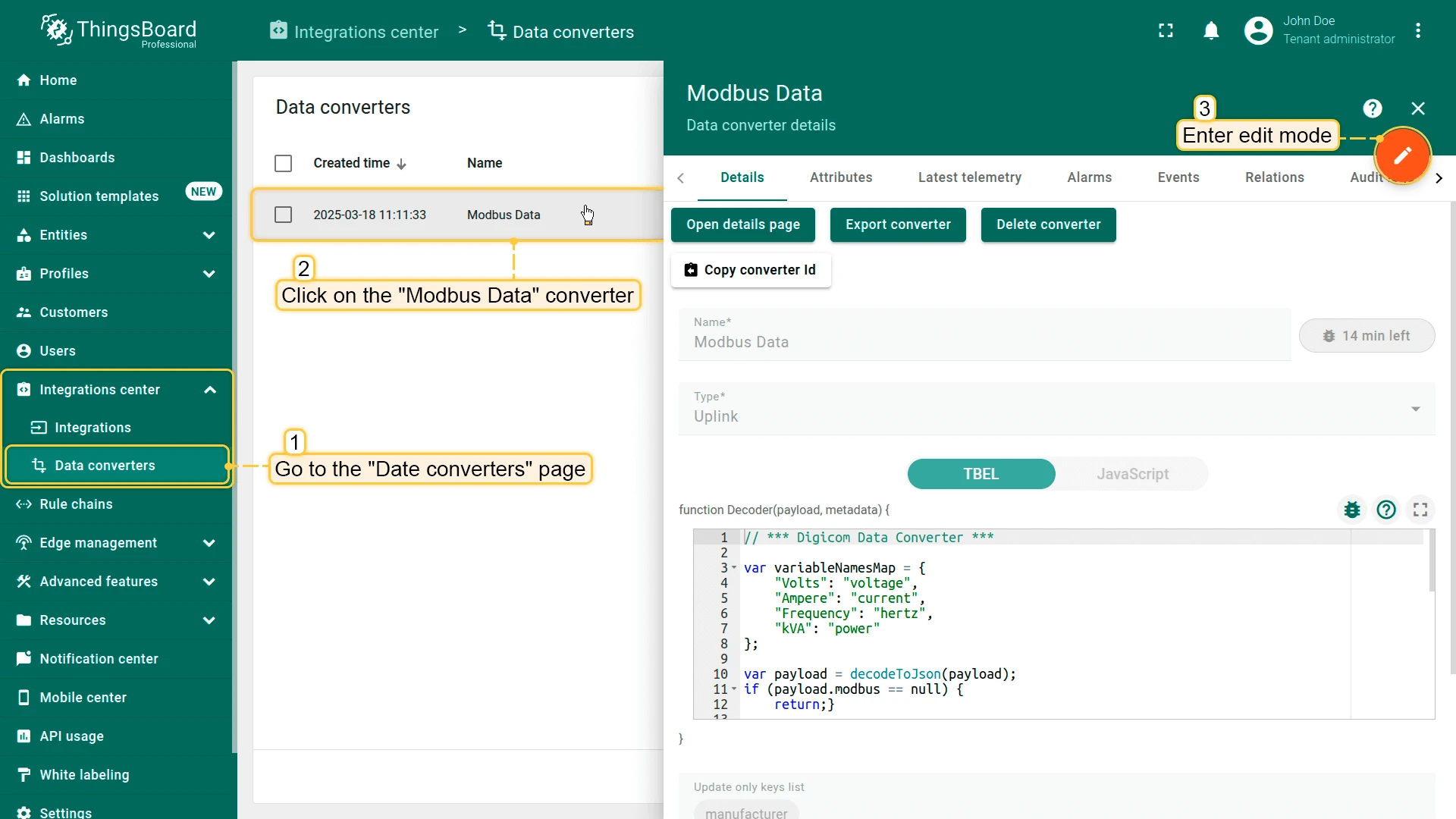
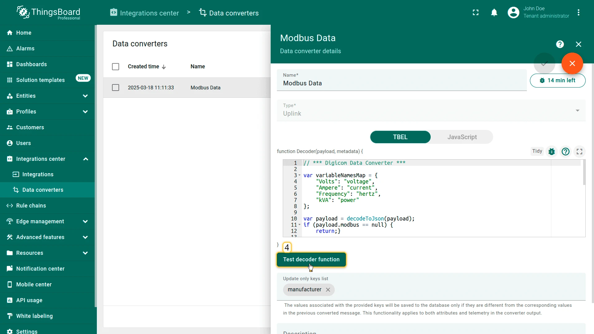
Go to Integrations center ⇾ Data converters, open the Modbus Data converter, and enter edit mode.

-
Click Test decoder function.
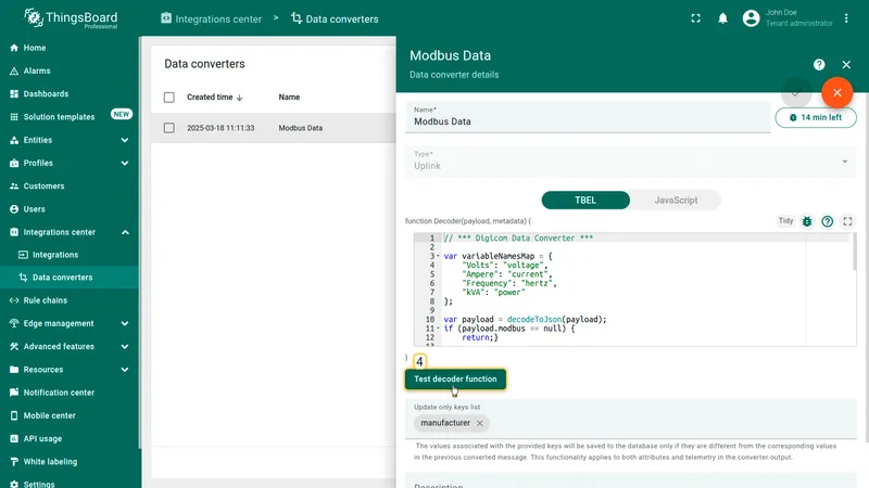
-
Paste the sample payload above into the Payload content tab and click Test. The Output tab should show telemetry with
voltage,current,hertz, andpowerkeys. Click Cancel, then exit edit mode.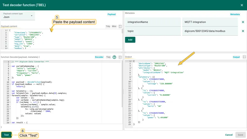
Device setup
Login
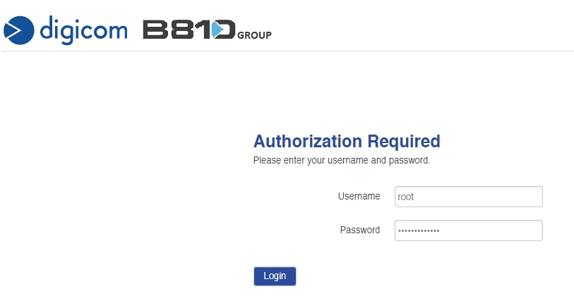
Log in to the DRN 500 web interface with your Username and Password.
This guide assumes the device already has Internet access configured and Modbus physical connections are in place.
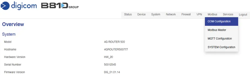
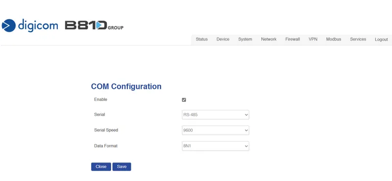
Modbus COM configuration
-
Select Modbus ⇾ COM Configuration from the menu.
-
Enable the Modbus serial interface and set type, speed, and data format to match the energy meter. Click Save.


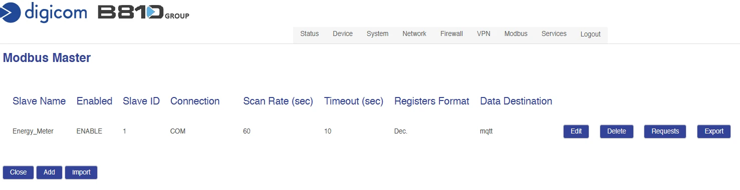
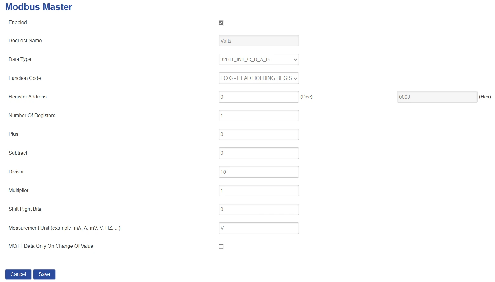
Modbus Master
-
Go to Modbus ⇾ Modbus Master and click Add.

-
Enable the profile and set Name, ID, Connection type, COM type, rates, and register formats. Set Data Destination to MQTT, then click Save.
-
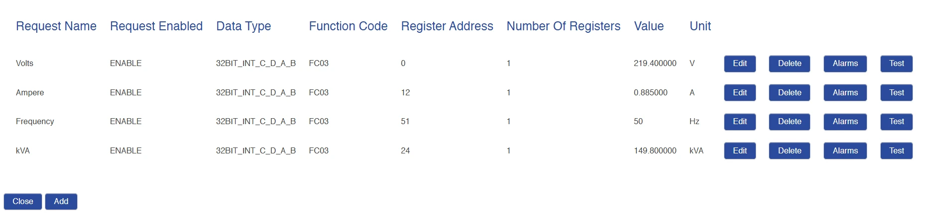
Click Requests to define the Modbus read registers.
-
Add a request for Volts (voltage) and click Save.

-
Repeat for Ampere (current), Frequency, and kVA (power) by clicking Add for each. The table should show four active requests with the Value column updating at the configured scan rate. Use Test for an immediate read.

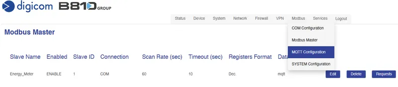
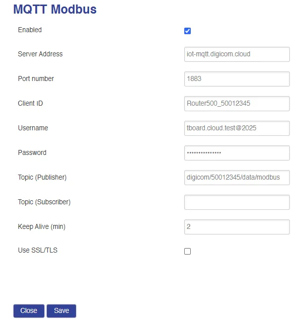
MQTT configuration
-
Select Modbus ⇾ MQTT Configuration from the menu.
-
Enter the external broker Server Address, Port, Username, and Password. The device publishes to:
digicom/<device SN>/data/modbusClick Save.


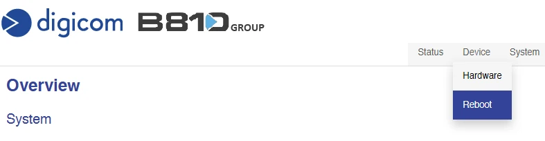
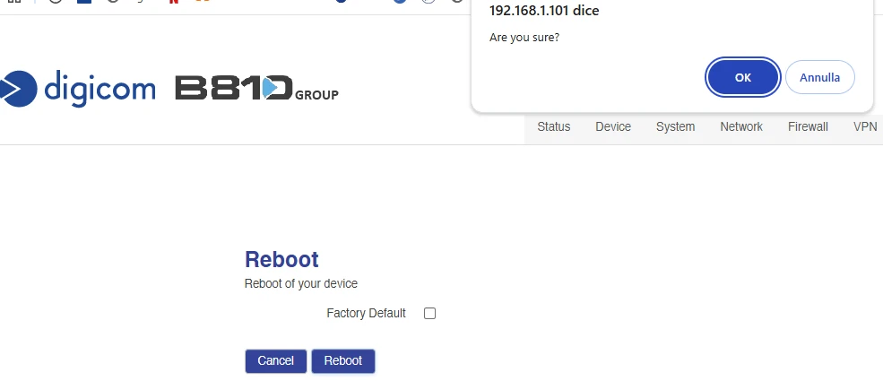
Reboot
Select Device ⇾ Reboot and confirm to apply the configuration. Wait for the device to come back online.
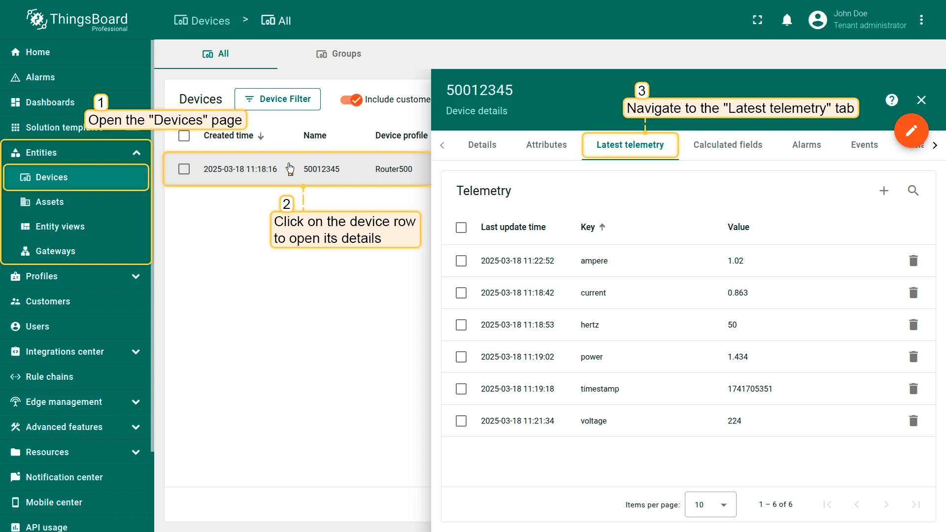
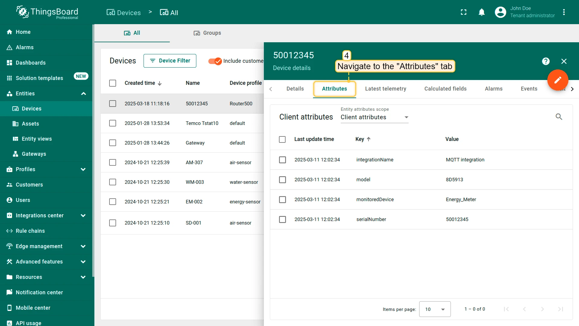
Verify device in ThingsBoard
After the DRN 500 publishes its first payload, a new device entry appears automatically in Entities ⇾ Devices.
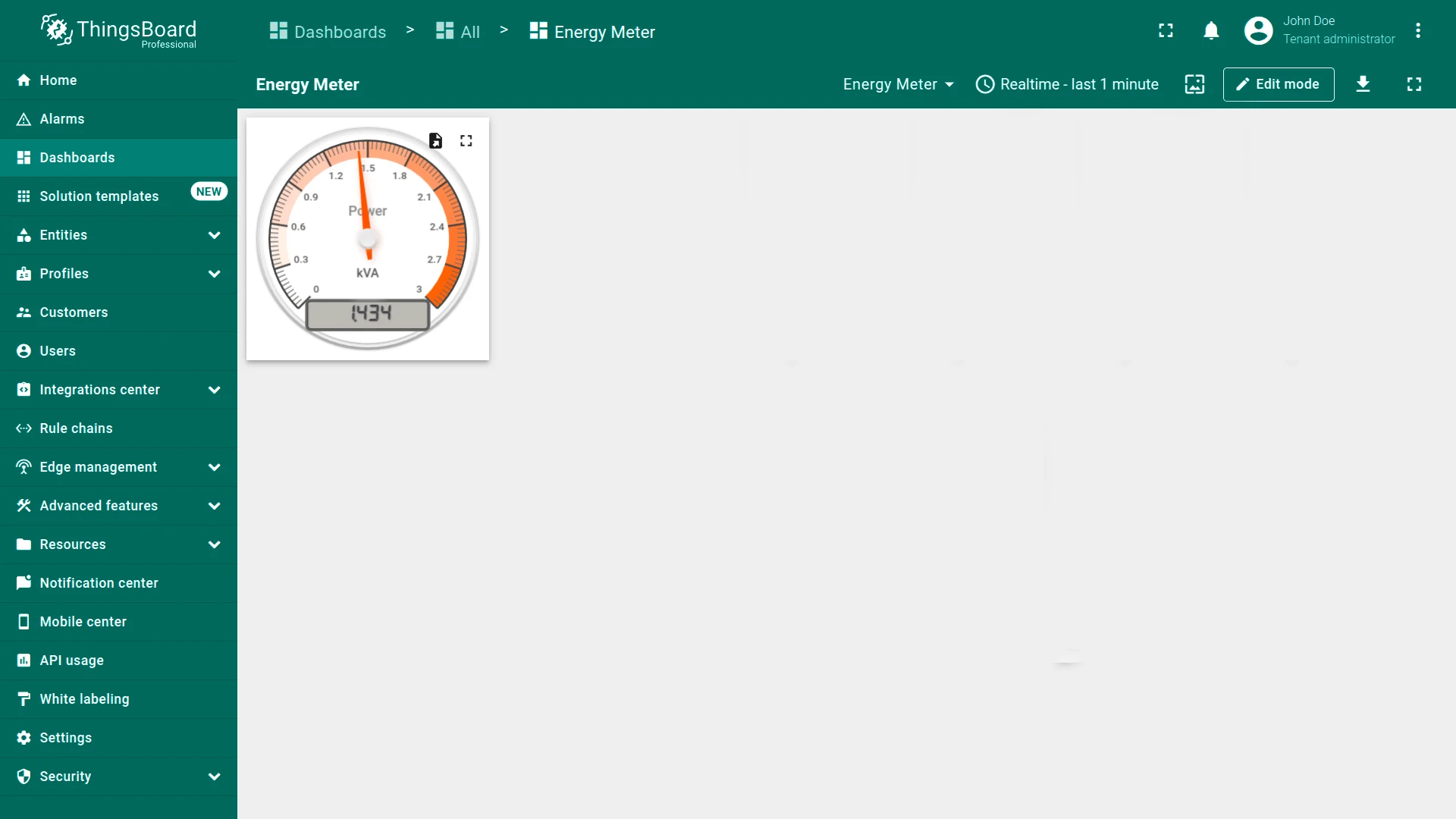
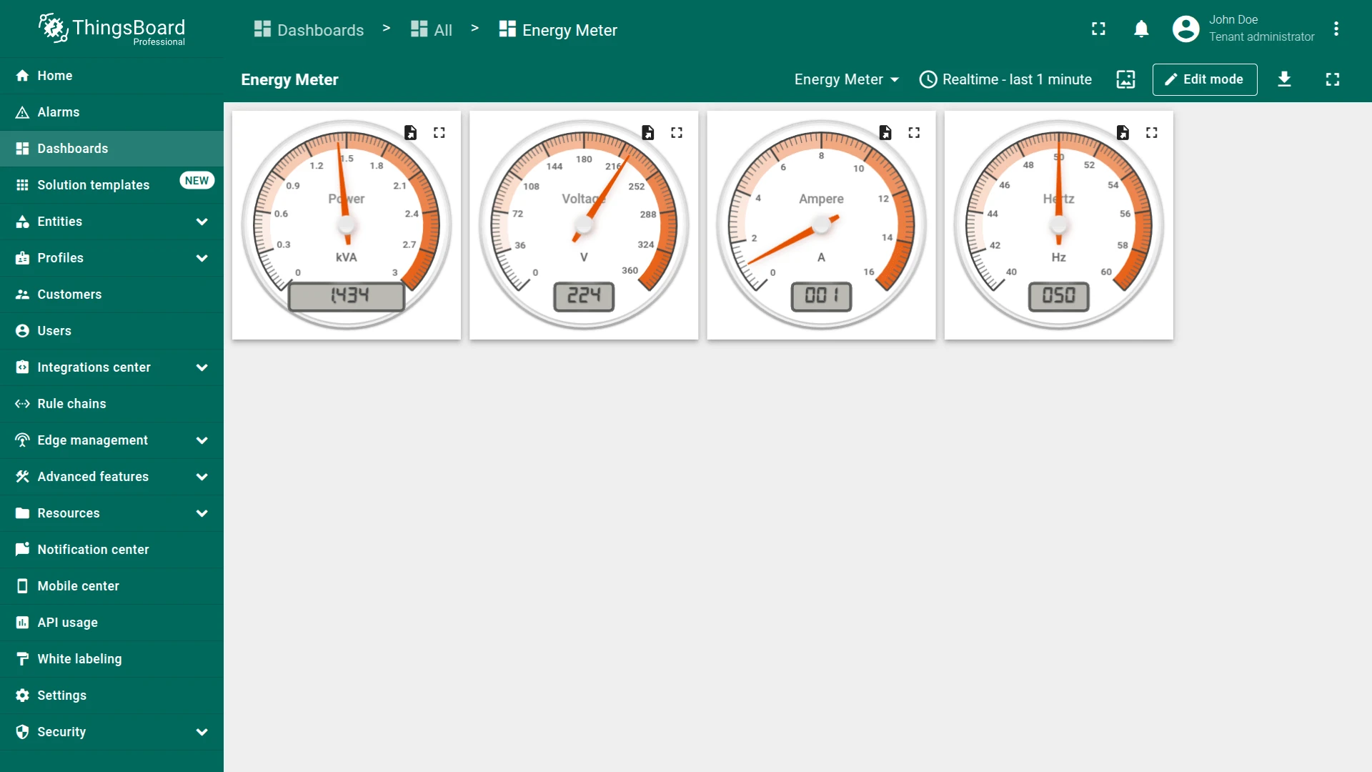
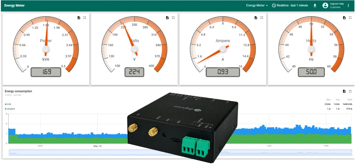
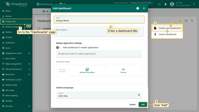
Create a dashboard
Use ThingsBoard dashboards to visualize the energy meter data in real time. The steps below create a dashboard with radial gauge widgets for voltage, current, frequency, and power.
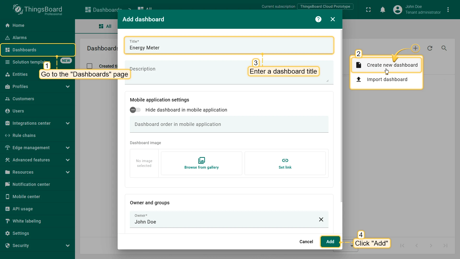
-
Go to Dashboards and click + Add dashboard ⇾ Create new dashboard. Enter a title and click Add.
-
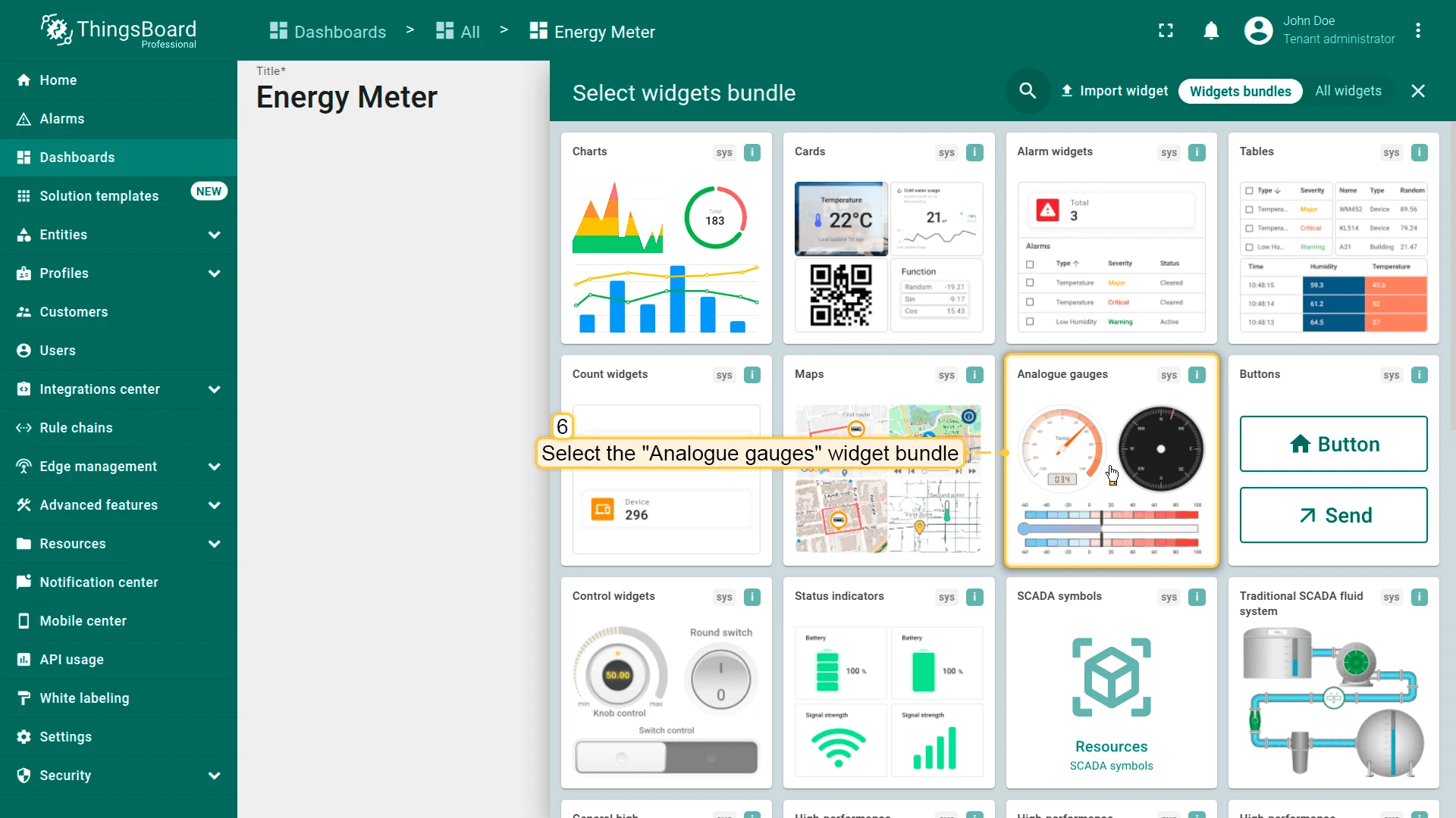
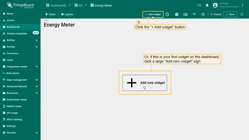
Click Add widget (or the center icon on an empty dashboard).
-
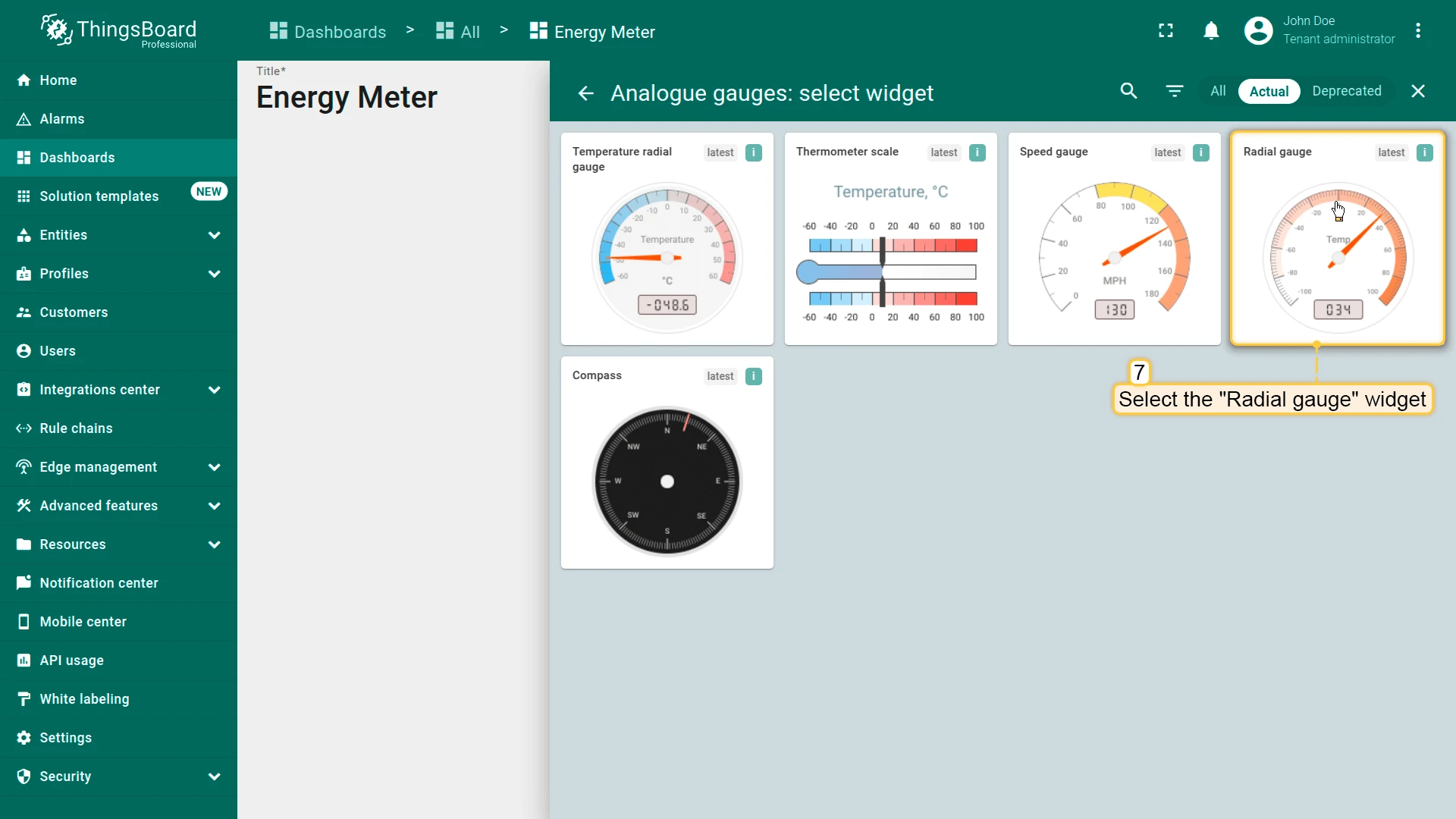
Open the Analogue gauges bundle and select Radial gauge.
-
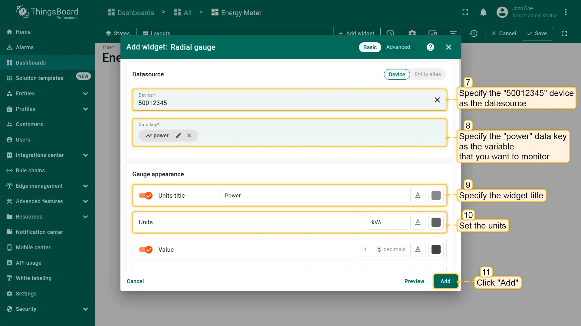
Set the device as the data source, set the data key to power, configure the title, units, and scale, then click Add.
-
Add similar widgets for voltage, current, and hertz. Position them and click Save.