- Introduction
- Create device on ThingsBoard
- Install required libraries and tools
- Connect device to ThingsBoard
- Check data on ThingsBoard
- Synchronize device state using client and shared attribute requests
- Control device using shared attributes
- Control device using RPC
- Conclusion
Introduction

The camera (OV3660) with 3 million pixels, DFOV 66.5° and shoot 2048x1536 resolution photo, built-in 140mAh battery and LED status indicator, featuring ultra-low power consumption design.
There is a reset button under the LED. It is possible to realize sleep and wake-up timing through RTC (BM8563). The standby current is only 2μA.
In this guide, we will discuss how to connect the ESP32-based boards to ThingsBoard.
In this guide, we will learn how to create device on Thingsboard, install required libraries and tools.
After this we will modify our code and upload it to the device, and check the results of our coding and check data on ThingsBoard using imported dashboard.
Our device will synchronize with ThingsBoard using client and shared attributes requests functionality.
Of course, we will control our device using provided functionality like shared attributes or RPC requests.
Prerequisites
To continue with this guide we will need the following:
Create device on ThingsBoard
For simplicity, we will provide the device manually using the UI.
-
Login to your ThingsBoard instance and navigate to the “Entities”. Then click the “Devices” page.
-
Click on the “+” icon in the top right corner of the table and then select “Add new device”.
-
Input device name. For example, “My Device”. No other changes required at this time. Click “Add” to add the device.
-
Your device has been added.
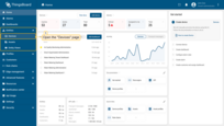
Login to your ThingsBoard instance and navigate to the “Entities”. Then click the “Devices” page.
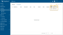
Click on the “+” icon in the top right corner of the table and then select “Add new device”.
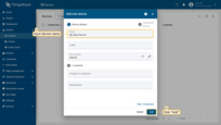
Input device name. For example, “My Device”. No other changes required at this time. Click “Add” to add the device.
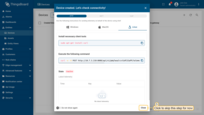
Your device has been added.
Install required libraries and tools
Install the board for Arduino IDE:
Go to File > Preferences and add the following URL to the Additional Boards Manager URLs field.
1
https://m5stack.oss-cn-shenzhen.aliyuncs.com/resource/arduino/package_m5stack_index.json
Next, go to Tools > Board > Board Manager and install the M5Stack by M5Stack Official board.
After the installation is complete, select the board by Board menu: Tools > Board > M5Stack > M5TimerCAM (Or M5Stack-Timer-CAM in older ESP-IDF versions).
Connect the device to computer using USB cable and select the port for the device: Tools > Port > /dev/ttyUSB0.
Port depends on operation system and may be different:
- for Linux it will be /dev/ttyUSBX
- for MacOS it will be usb.serialX.. or usb.modemX..
- for Windows - COMX.
To install ThingsBoard Arduino SDK - we will need to do the following steps:
-
Go to “Tools” tab and click on “Manage libraries”.
-
Put “ThingsBoard” into the search box and press “INSTALL” button for the found library.
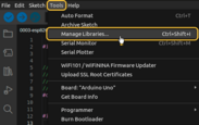
Go to “Tools” tab and click on “Manage libraries”.
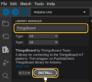
Put “ThingsBoard” into the search box and press “INSTALL” button for the found library.
At this point, we have installed all required libraries and tools.
Connect device to ThingsBoard
To connect your device, you’ll first need to get its credentials. While ThingsBoard supports a variety of device credentials, for this guide, we will use the default auto-generated credentials, which is an access token.
-
Click on the device row in the table to open device details.
-
Click “Copy access token”. The token will be copied to your clipboard. Please save it in a safe place.
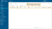
Click on the device row in the table to open device details.
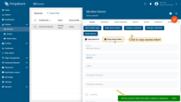
Click “Copy access token”. The token will be copied to your clipboard. Please save it in a safe place.
Now it’s time to program the board to connect to ThingsBoard.
To do this, you can use the code below. It contains all required functionality for this guide.
Necessary variables for connection:
| Variable name | Default value | Description |
|---|---|---|
| WIFI_SSID | YOUR_WIFI_SSID | Your WiFi network name. |
| WIFI_PASSWORD | YOUR_WIFI_PASSWORD | Your WiFi network password. |
| TOKEN | YOUR_DEVICE_ACCESS_TOKEN | Access token from device. Obtaining process described in #connect-device-to-thingsboard |
| THINGSBOARD_SERVER | demo.thingsboard.io | Your ThingsBoard host or ip address. |
| THINGSBOARD_PORT | 1883U | ThingsBoard server MQTT port. Can be default for this guide. |
| MAX_MESSAGE_SIZE | 100U*1024 | Maximal size of MQTT messages. Should be more than picture size + ~1024 or more. |
| SERIAL_DEBUG_BAUD | 1883U | Baud rate for serial port. Can be default for this guide. |
| DEMO_MODE | 1 | If you want to use demo.thingsboard.io set this value to 1. This reduces the resolution, quality and cut the encoded photo to avoid size limit. |
1
2
3
4
5
6
7
8
9
10
11
12
13
14
...

constexpr char WIFI_SSID[] = "YOUR_WIFI_SSID";
constexpr char WIFI_PASSWORD[] = "YOUR_WIFI_PASSWORD";

constexpr char TOKEN[] = "YOUR_ACCESS_TOKEN";

constexpr char THINGSBOARD_SERVER[] = "demo.thingsboard.io";
constexpr uint16_t THINGSBOARD_PORT = 1883U;

constexpr uint32_t MAX_MESSAGE_SIZE = 100U * 1024;
constexpr uint32_t SERIAL_DEBUG_BAUD = 115200U;

...
Send data part (By default the example sends random value for temperature key and some WiFi information):
1
2
3
4
5
6
7
8
...
    tb.sendTelemetryData("temperature", random(10, 20));
    tb.sendAttributeData("rssi", WiFi.RSSI());
    tb.sendAttributeData("bssid", WiFi.BSSIDstr().c_str());
    tb.sendAttributeData("localIp", WiFi.localIP().toString().c_str());
    tb.sendAttributeData("ssid", WiFi.SSID().c_str());
    tb.sendAttributeData("channel", WiFi.channel());
...
Then upload the code to the device by pressing Upload button or keyboard combination Ctrl+U.
Check data on ThingsBoard
ThingsBoard provides the ability to create and customize interactive visualizations (dashboards) for monitoring and managing data and devices.
Through ThingsBoard dashboards, you can efficiently manage and monitor your IoT devices and data. So, we will create the dashboard, for our device.
To add the dashboard to ThingsBoard, we need to import it. To import a dashboard, follow these steps:
- First download the Check and control device data dashboard file.
-
Navigate to the “Dashboards” page and click the “+” button in the upper right corner of the page and select “Import dashboard”.
-
In the dashboard import window, upload the JSON file and click “Import” button.
-
Dashboard has been imported.
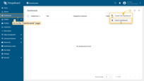
Navigate to the “Dashboards” page and click the “+” button in the upper right corner of the page and select “Import dashboard”.
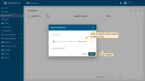
In the dashboard import window, upload the JSON file and click “Import” button.
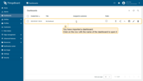
Dashboard has been imported.
The Check and control device data dashboard structure:
-
To check the data from our device we need to open the imported dashboard by clicking on it in the table.
-
The view of checking data and controlling our device dashboard.
-
Received attributes from device.
-
Device information from the ThingsBoard server.
-
Widget to see the history of LED mode changes.
-
Widget to see the history of our emulated temperature.
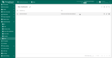
To check the data from our device we need to open the imported dashboard by clicking on it in the table.
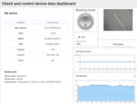
The view of checking data and controlling our device dashboard.
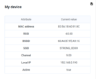
Received attributes from device.

Device information from the ThingsBoard server.
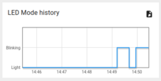
Widget to see the history of LED mode changes.
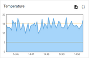
Widget to see the history of our emulated temperature.
Synchronize device state using client and shared attribute requests
In order to get the state of the device from ThingsBoard during booting we have functionality to do this in the code.
Below are the relevant parts of the code example:
- Connecting modules to use API functionality:
1
2
3
4
5
6
7
8
9
10
11
...
#include <AttributeRequest.h>
...
Attribute_Request<2U, MAX_ATTRIBUTES> attr_request;
...
const std::array<IAPI_Implementation*, ...> apis = {
  ...
  &attr_request,
  ...
};
...
We need to define what API we will use in our code.
- Attribute callbacks:
1
2
3
4
5
6
7
8
9
10
11
12
13
14
15
16
17
18
19
20
21
22
23
24
25
26
27
28
29
30
31
32
33
34
35
36
37
...
void processSharedAttributes(const JsonObjectConst &data) {
  for (auto it = data.begin(); it != data.end(); ++it) {
    if (strcmp(it->key().c_str(), BLINKING_INTERVAL_ATTR) == 0) {
      const uint16_t new_interval = it->value().as<uint16_t>();
      if (new_interval >= BLINKING_INTERVAL_MS_MIN && new_interval <= BLINKING_INTERVAL_MS_MAX) {
        blinkingInterval = new_interval;
        Serial.print("Updated blinking interval to: ");
        Serial.println(new_interval);
      }
    } else if(strcmp(it->key().c_str(), LED_STATE_ATTR) == 0) {
      ledState = it->value().as<bool>();
      digitalWrite(LED_BUILTIN, ledState ? HIGH : LOW);
      Serial.print("Updated state to: ");
      Serial.println(ledState);
    }
  }
  attributesChanged = true;
}

void processClientAttributes(const JsonObjectConst &data) {
  for (auto it = data.begin(); it != data.end(); ++it) {
    if (strcmp(it->key().c_str(), LED_MODE_ATTR) == 0) {
      const uint16_t new_mode = it->value().as<uint16_t>();
      ledMode = new_mode;
    }
  }
}
...
// Attribute request did not receive a response in the expected amount of microseconds
void requestTimedOut() {
  Serial.printf("Attribute request timed out did not receive a response in (%llu) microseconds. Ensure client is connected to the MQTT broker and that the keys actually exist on the target device\n", REQUEST_TIMEOUT_MICROSECONDS);
}
...
const Attribute_Request_Callback<MAX_ATTRIBUTES> attribute_shared_request_callback(&processSharedAttributes, REQUEST_TIMEOUT_MICROSECONDS, &requestTimedOut, SHARED_ATTRIBUTES_LIST);
const Attribute_Request_Callback<MAX_ATTRIBUTES> attribute_client_request_callback(&processClientAttributes, REQUEST_TIMEOUT_MICROSECONDS, &requestTimedOut, CLIENT_ATTRIBUTES_LIST);
...
We have three callbacks:
- Shared Attributes Callback: This callback is specific to shared attributes. Its primary function is to receive a response containing the blinking interval, which determines the appropriate blinking period.;
- Client Attributes Callback: This callback is specific to client attributes. It receives information regarding the mode and state of the LED. Once this data is received, the system saves and sets these parameters.
- Request Timeout Callback: This callback is triggered when the request for attribute data times out. It is used to handle the timeout event.
This functionality allows us to keep the actual state after rebooting.
- Attribute requests:
1
2
3
4
5
6
7
8
9
10
11
12
13
...
  // Request current states of shared attributes
  if (!attr_request.Shared_Attributes_Request(attribute_shared_request_callback)) {
    Serial.println("Failed to request for shared attributes");
    return;
  }

  // Request current states of client attributes
  if (!attr_request.Client_Attributes_Request(attribute_client_request_callback)) {
    Serial.println("Failed to request for client attributes");
    return;
  }
...
In order for our callbacks to receive the data, we have to send a request to ThingsBoard.
Control device using shared attributes
Also we can change the period of the blinking using shared attribute update functionality.
-
To change period of the blinking we just need to change the value on our dashboard.
-
After applying by pressing check mark you will see a confirmation message.
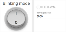
To change period of the blinking we just need to change the value on our dashboard.
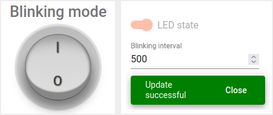
After applying by pressing check mark you will see a confirmation message.
In order to change state when blinking is disabled - we can use the switch in the same widget:
-
It can be done only when the blinking mode is disabled.
To reach this, we have a variable “blinkingInterval” used in the following parts of the code:
- Connecting modules to use API functionality:
1
2
3
4
5
6
7
8
9
10
11
...
#include <AttributeRequest.h>
...
Attribute_Request<2U, MAX_ATTRIBUTES> attr_request;
...
const std::array<IAPI_Implementation*, ...> apis = {
  ...
  &shared_update
  ...
};
...
To use attribute requests functionality we need to include related module and define it as a part of used API.
- Callback for shared attributes update:
1
2
3
4
5
6
7
8
9
10
11
12
13
14
15
16
17
18
19
20
21
22
23
24
25
26
27
28
29
...

void processSharedAttributes(const JsonObjectConst &data) {
  for (auto it = data.begin(); it != data.end(); ++it) {
    if (strcmp(it->key().c_str(), BLINKING_INTERVAL_ATTR) == 0) {
      const uint16_t new_interval = it->value().as<uint16_t>();
      if (new_interval >= BLINKING_INTERVAL_MS_MIN && new_interval <= BLINKING_INTERVAL_MS_MAX) {
        blinkingInterval = new_interval;
        Serial.print("Updated blinking interval to: ");
        Serial.println(new_interval);
      }
    } else if(strcmp(it->key().c_str(), LED_STATE_ATTR) == 0) {
      ledState = it->value().as<bool>();
      digitalWrite(LED_BUILTIN, ledState ? HIGH : LOW);
      Serial.print("Updated state to: ");
      Serial.println(ledState);
    }
  }
  attributesChanged = true;
}

...
// Attribute request did not receive a response in the expected amount of microseconds
void requestTimedOut() {
  Serial.printf("Attribute request timed out did not receive a response in (%llu) microseconds. Ensure client is connected to the MQTT broker and that the keys actually exist on the target device\n", REQUEST_TIMEOUT_MICROSECONDS);
}
...
const Attribute_Request_Callback<MAX_ATTRIBUTES> attribute_shared_request_callback(&processSharedAttributes, REQUEST_TIMEOUT_MICROSECONDS, &requestTimedOut, SHARED_ATTRIBUTES_LIST);
...
- Subscribing for shared attributes update:
1
2
3
4
5
6
...
    if (!shared_update.Shared_Attributes_Request(attribute_shared_request_callback)) {
      Serial.println("Failed to request for shared attributes");
      return;
    }
...
- Part of code to blink:
1
2
3
4
5
6
7
8
9
10
11
12
13
14
...

  if (ledMode == 1 && millis() - previousStateChange > blinkingInterval) {
    previousStateChange = millis();
    ledState = !ledState;
    digitalWrite(LED_BUILTIN, ledState);
    tb.sendTelemetryData(LED_STATE_ATTR, ledState);
    tb.sendAttributeData(LED_STATE_ATTR, ledState);
    if (LED_BUILTIN == 99) {
      Serial.print("LED state changed to: ");
      Serial.println(ledState);
    }
  }
...
You can change the logic to reach your goals and add processing for your attributes.
Control device using RPC
You can manually change state of the LED and change mode between continuous lightning and blinking. To do this, you can use the following parts of our dashboard:
-
Change LED state using switch widget to continuous lightning.
-
Change LED state using round switch widget to blinking mode.
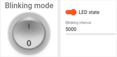
Change LED state using switch widget to continuous lightning.

Change LED state using round switch widget to blinking mode.
Please note that you can change the LED state only if blinking mode is disabled.
In the code example we have functionality to handle RPC commands.
To get ability to control the device we have used the following parts of the code:
- Connecting modules to use API functionality:
1
2
3
4
5
6
7
8
9
10
11
12
...
#include <Server_Side_RPC.h>
...
Server_Side_RPC<..., ...> rpc;
...

const std::array<IAPI_Implementation*, ...> apis = {
    ...
    &rpc,
    ...
    }
...
To use RPC we need to include related module and define it as a part of used API.
- Callback for RPC requests:
1
2
3
4
5
6
7
8
9
10
11
12
13
14
15
16
17
18
19
20
21
22
23
24
25
26
27
28
29
30
31
32
33
34
35
36
...

void processSetLedMode(const JsonVariantConst &data, JsonDocument &response) {
  Serial.println("Received the set led state RPC method");

  // Process data
  int new_mode = data;

  Serial.print("Mode to change: ");
  Serial.println(new_mode);
  StaticJsonDocument<1> response_doc;

  if (new_mode != 0 && new_mode != 1) {
    response_doc["error"] = "Unknown mode!";
    response.set(response_doc);
    return;
  }

  ledMode = new_mode;

  attributesChanged = true;


  response_doc["newMode"] = (int)ledMode;
  // Returning current mode
  response.set(response_doc);
}

...

const std::array<RPC_Callback, 2U> callbacks = {
  RPC_Callback{ "setLedMode", processSetLedMode },
  RPC_Callback{ "takePicture", processTakePicture }
};

...
- Subscribing for RPC requests:
1
2
3
4
5
6
...
    if (!rpc.RPC_Subscribe(callbacks.cbegin(), callbacks.cend())) {
      Serial.println("Failed to subscribe for RPC");
      return;
    }
...
Such as the board has included camera we can take a picture and see it on the dashboard.
-
You can take a picture from camera module, by pressing the button on ThingsBoard dashboard.
To take a picture we send “takePicture” RPC to the device.
The following part of the code takes a picture.
1
2
3
4
5
6
7
8
9
10
11
12
13
...

bool captureImage() {
  camera_fb_t *fb = NULL;
  fb = esp_camera_fb_get();
  if (!fb) {
    return false;
  }
  encode((uint8_t *)fb->buf, fb->len);
  esp_camera_fb_return(fb);
  return true;
}
...
We are unable to send a raw bytes array of the photo in JSON, so we are also encoding bytes to Base64:
1
2
3
4
5
6
7
8
9
...
void encode(const uint8_t *data, size_t length) {
  size_t size = base64_encode_expected_len(length) + 1;
  base64_encodestate _state;
  base64_init_encodestate(&_state);
  int len = base64_encode_block((char *)&data[0], length, &imageBuffer[0], &_state);
  len = base64_encode_blockend((imageBuffer + len), &_state);
}
...
Our encoded picture will be sent in the main loop:
1
2
3
4
5
6
...
if (sendPicture) {
tb.sendTelemetryData(PICTURE_ATTR, imageBuffer);
sendPicture = false;
}
...
You can change the code to reach your goals and add processing for your RPC commands.
Conclusion
With the knowledge outlined in this guide, you can easily connect your M5Stack Timer Camera X and send data to ThingsBoard.
Explore the platform documentation to learn more about key concepts and features. For example, configure alarm rules or dashboards.


