ORB-C1-G

ORB-C1-G
Senquip
- Platform
- ThingsBoard
- Hardware Type
- Other devices
- Connectivity
- Wi-Fi, GSM/GPRS, CAN Bus, Modbus, RS-485, RS-232
- Industry
- Transportation & Logistics, Industrial Manufacturing, Agriculture, Energy Management
- Use Case
- Fleet Tracking, Smart Metering, Smart Farming, Environment Monitoring
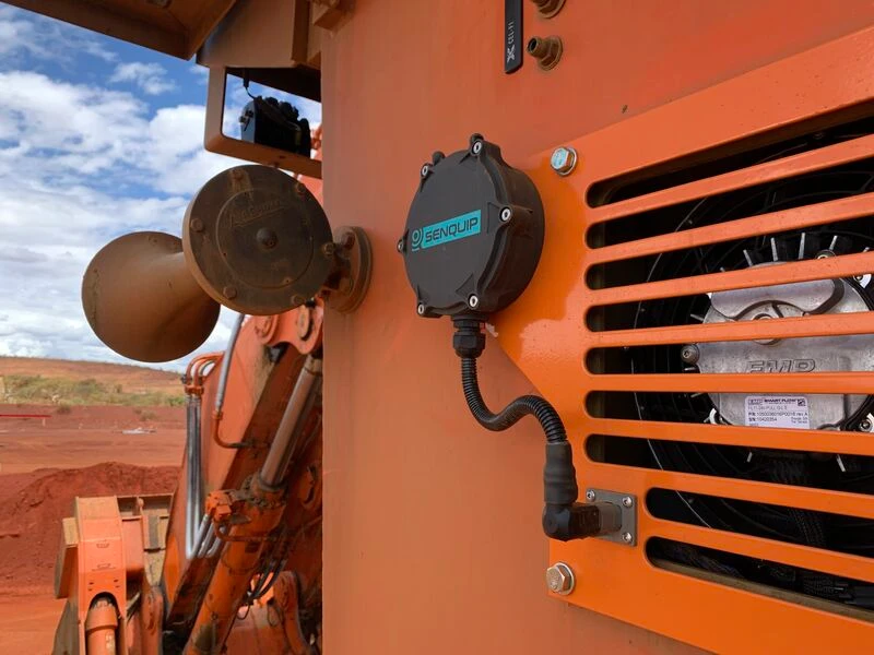
Introduction
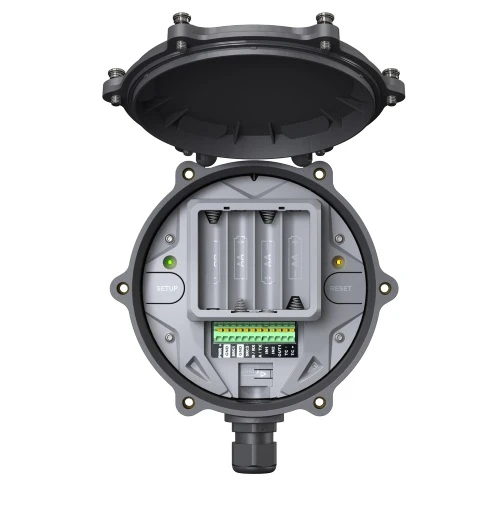
The Senquip ORB-C1-G is a rugged, programmable telemetry device that connects to industrial sensors and systems including MODBUS, CAN Bus, current, voltage, and frequency inputs. It can maintain a simultaneous connection to the Senquip Portal and a third-party endpoint, allowing configuration changes and firmware updates from the Portal while sending measured data to ThingsBoard.
This guide describes how to send location, temperature, and CAN Bus data from an ORB-C1-G to ThingsBoard over MQTT, and visualize the data on a dashboard.
For the full hardware reference, see the ORB-C1 User Guide and Quick Start Guide.
Prerequisites
Hardware:
- Senquip ORB-C1-G — 1×
Accounts:
- Senquip Portal account with a registered device, configured for Wi-Fi or cellular connectivity
- ThingsBoard instance: use ThingsBoard Cloud or install a local server
Hardware overview
| Pin | Name | Terminal marking | Description |
|---|---|---|---|
| 1 | Positive voltage in | PWR+ | Positive system power (permanent or intermittent, like solar) |
| 2 | Negative voltage in | GND | Negative system power or ground |
| 3 | Source 1 | SRC1 | Switchable output with current measurement for 4–20 mA sensors |
| 4 | Ground | GND | Spare ground for sensor connection |
| 5 | Source 2 | SRC2 | Switchable output with current measurement for 4–20 mA sensors |
| 6 | Serial in | B / RX | RS485B in RS485 mode; receive in RS232 mode |
| 7 | Serial out | A / TX | RS485A in RS485 mode; transmit in RS232 mode |
| 8 | Input 1 | IN1 | Analog or digital input with edge detect capability |
| 9 | Input 2 | IN2 | Analog or digital input |
| 10 | Output | OUT1 | Open collector output |
| 11 | CAN Bus High | CAN H | CAN Bus high connection |
| 12 | CAN Bus Low | CAN L | CAN Bus low connection |
Configure ThingsBoard
Create a device
-
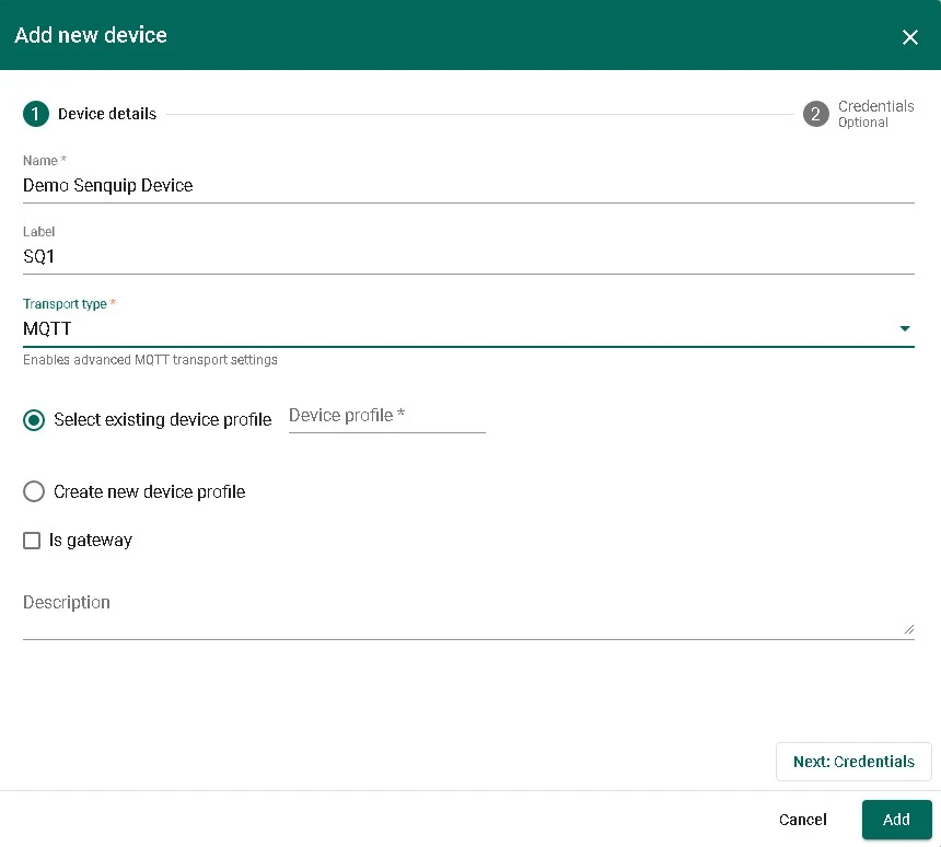
Go to Entities ⇾ Devices and click + Add device ⇾ Add new device. Enter a name (like
Demo Senquip Device) and a short label (likeSQ1). Select MQTT as the transport type and click Next: Credentials.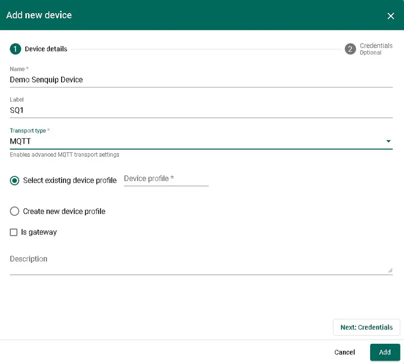
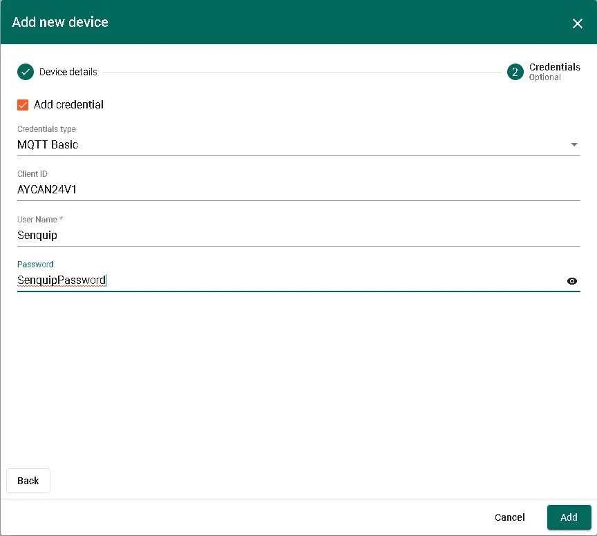
-
Select MQTT Basic as the credentials type. Enter the Client ID, User Name, and Password that you will also configure on the ORB-C1-G. Click Add.

Configure the ORB-C1-G
All configuration is performed on the Senquip Portal.
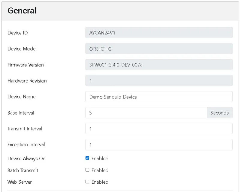
General setup
-
Give the device a meaningful name: Setup > General > Name =
Demo Senquip Device. -
Set the measurement and transmission interval to 5 seconds: Setup > General > Base Interval =
5. -
Enable the GPS peripheral and set it to measure on every base interval: Setup > Internal > GPS > Interval =
1. -
Enable the CAN peripheral and set it to measure on every base interval: Setup > External > CAN > Interval =
1. If this is the only CAN device on the network, select Tx Enable so the ORB-C1-G acknowledges CAN messages. -
Click Save.

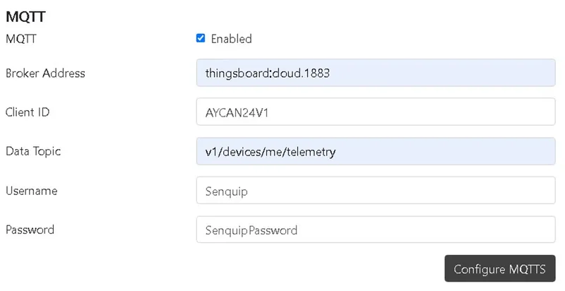
Configure the MQTT endpoint
-
Enable the MQTT endpoint and configure the connection:
Setting Value Setup > Endpoint > MQTT Enabled Broker Address thingsboard.cloud:1883(or your ThingsBoard server address)Client ID The Client ID entered in ThingsBoard credentials Data Topic v1/devices/me/telemetryUsername The User Name entered in ThingsBoard credentials Password The Password entered in ThingsBoard credentials Click Save.

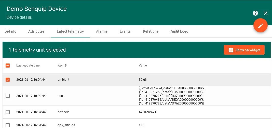
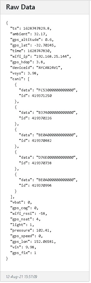
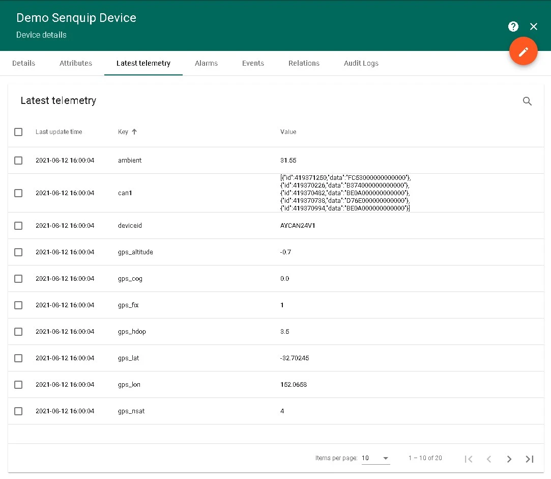
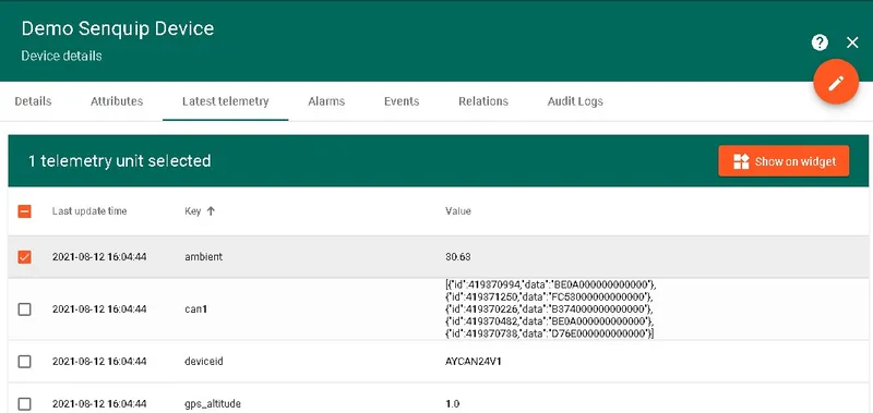
Verify data
Senquip devices send data in JSON format. Each measurement has a key and a value — for example, GPS latitude uses the key gps_lat with a value like -32.70245. Nested data such as CAN messages appears as separate rows.
-
In ThingsBoard, go to Entities > Devices, open the device, and navigate to the Latest telemetry tab. ThingsBoard automatically parses the JSON payload into a table of keys and values, including the nested CAN identifiers.

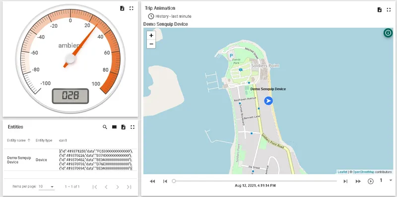
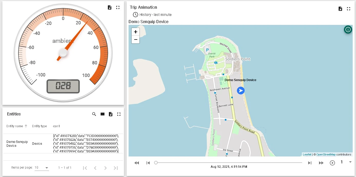
Build a dashboard
-
On the Latest telemetry tab, click a data key row and press Show on widget.
-
Choose a widget bundle matching your data type (for temperature, use Analog gauges), then click Add to dashboard. Create a new dashboard named
Senquip Demoor add to an existing one.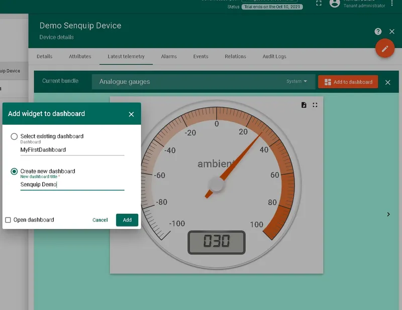
-
Repeat for additional telemetry keys. For map widgets, configure the Latitude and Longitude under advanced settings to use the
gps_latandgps_lonkeys. Resize and arrange widgets as needed and click Save.