Aggregate Telemetry from Related Devices
This guide shows how to use a Related Entities Aggregation calculated field to calculate telemetry from multiple related devices, aggregate the values, and store the result on the parent asset.
Use case
Section titled “Use case”A building contains multiple water meters. Each meter sends telemetry: waterConsumption.
Goal: totalWaterConsumption calculated across all meters in the building.
ThingsBoard:
- finds all devices related to Building A via Contains relations
- sums up
waterConsumptionfrom all meters - stores the result as
totalWaterConsumptionon Building A
Step 1. Create devices and asset
Section titled “Step 1. Create devices and asset”Create an asset to represent the building:
- Name:
Building A - Asset profile:
building
Create two devices with the Water Meter device profile:
- Name:
Water Meter A1 - Name:
Water Meter A2


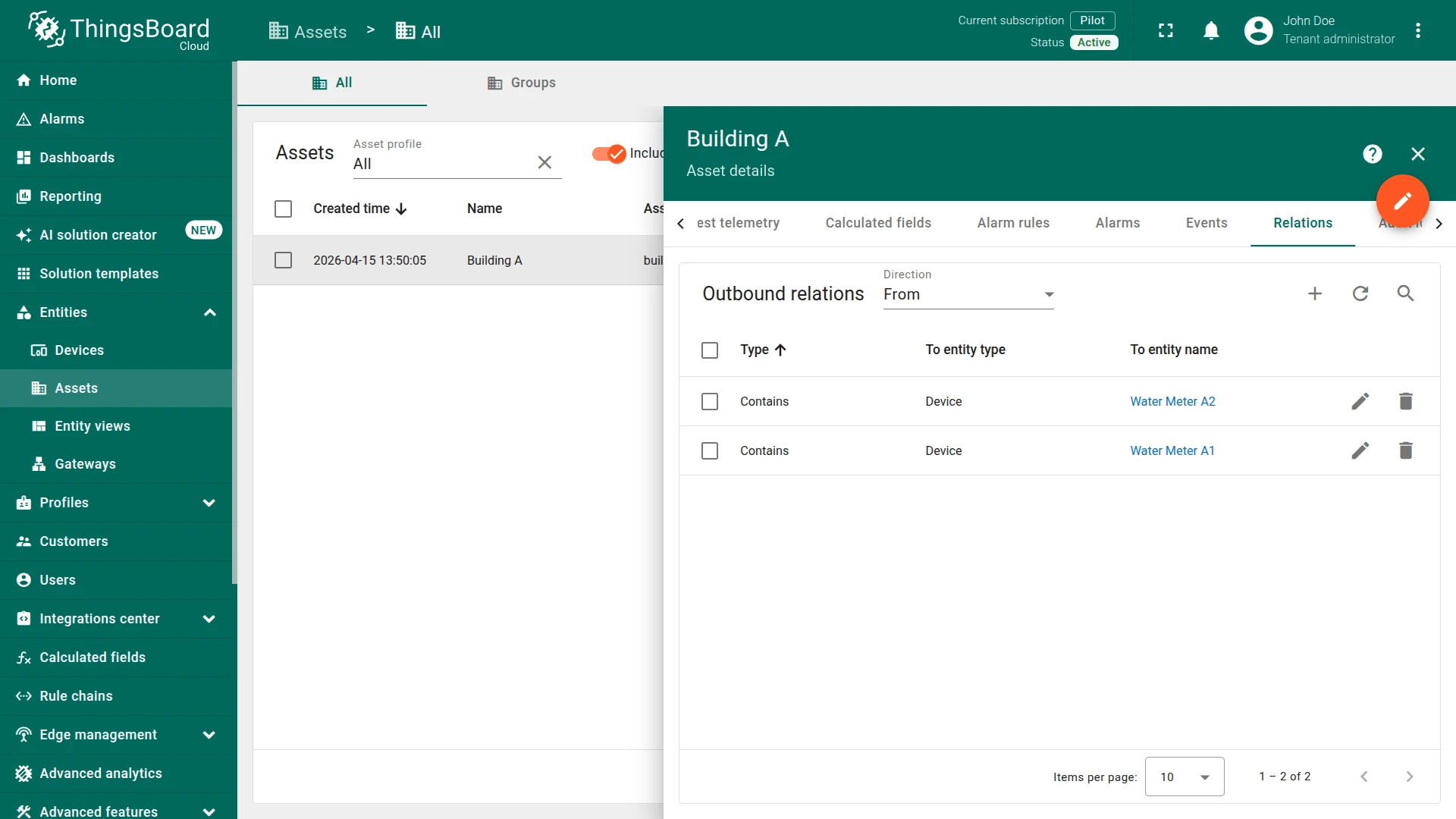
Step 2. Create relations
Section titled “Step 2. Create relations”Link both water meters to the building using outbound Contains relations:
- Open Building A details.
- Go to the Relations tab.
- Add an outbound Contains relation to Water Meter A1.
- Add an outbound Contains relation to Water Meter A2.
Step 3. Create calculated field
Section titled “Step 3. Create calculated field”You can import a ready-made calculated field or build it manually.
Option 1. Import calculated field
-
Download the Building Total Water Consumption calculated field as JSON file and import it into your instance.
Option 2. Create manually
- Navigate to Calculated fields and click + Add calculated field.
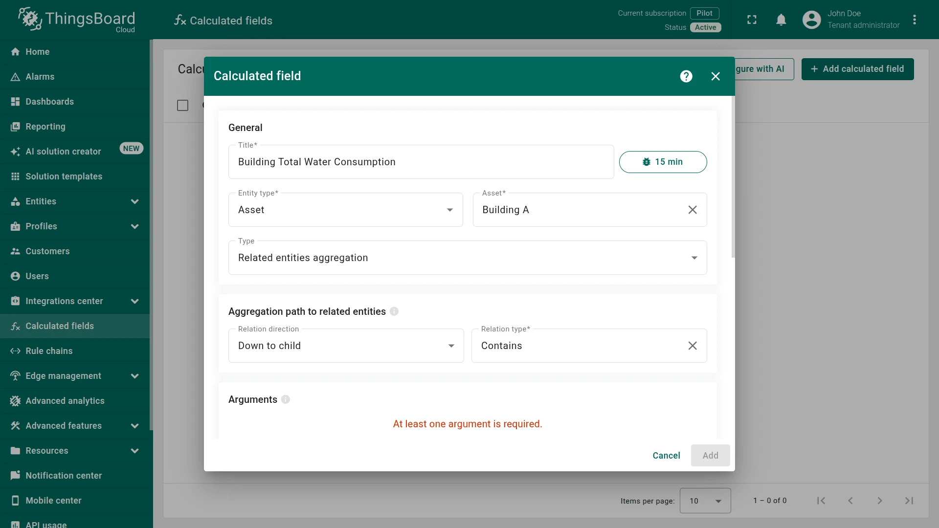
General settings
Section titled “General settings”- Title:
Building Total Water Consumption - Entity type:
Asset - Entity:
Building A - Type:
Related entities aggregation
Aggregation path to related entities
Section titled “Aggregation path to related entities”- Relation direction:
Down to child - Relation type:
Contains
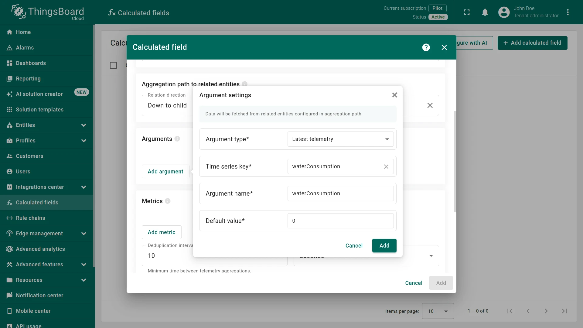
Argument
Section titled “Argument”Click Add argument and configure it to read waterConsumption from each related device:
- Argument type:
Latest telemetry - Time series key:
waterConsumption - Argument name:
waterConsumption - Default value:
0
Metric
Section titled “Metric”Click Add metric and configure the aggregation:
- Metric name:
totalWaterConsumption - Aggregation:
Sum - Value source:
Key - Argument name:
waterConsumption


Output
Section titled “Output”- Output type:
Time series - Strategy:
Process right away
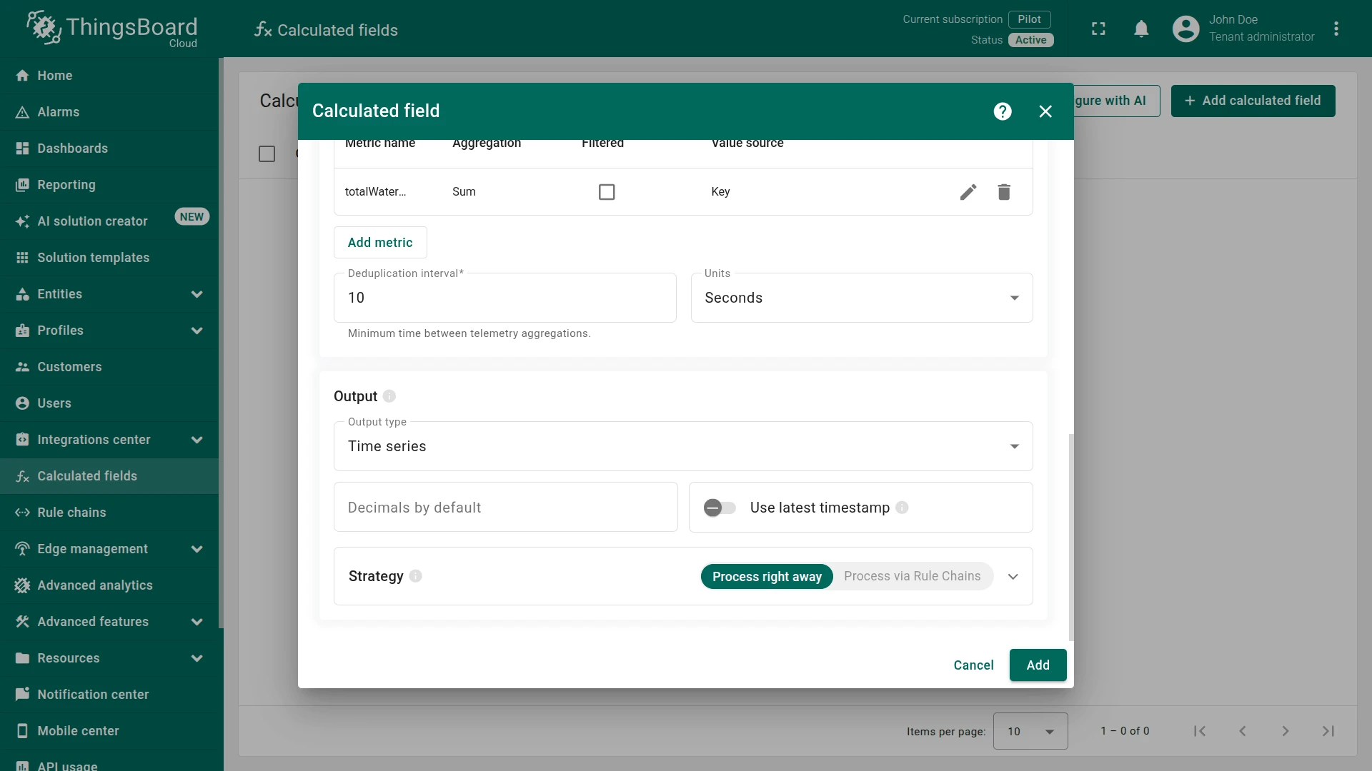
Click Add to save.
Step 4. Verify the result
Section titled “Step 4. Verify the result”Send waterConsumption telemetry to both meters. Replace $ACCESS_TOKEN with the device access token.
Water Meter A1:
curl -v -X POST -d '{"waterConsumption": 2.75}' https://$THINGSBOARD_HOST/api/v1/$ACCESS_TOKEN/telemetry --header "Content-Type:application/json"Water Meter A2:
curl -v -X POST -d '{"waterConsumption": 6.25}' https://$THINGSBOARD_HOST/api/v1/$ACCESS_TOKEN/telemetry --header "Content-Type:application/json"

The calculated field reads the latest value from each related device, sums them, and writes totalWaterConsumption as a time series key on Building A.
Expected result: Open Building A ⇾ Latest telemetry to confirm the aggregated value appears. The totalWaterConsumption value is 9.0 (2.75 + 6.25), updated automatically whenever new data arrives from either meter.

See also
Section titled “See also”- Related entities aggregation — full feature reference
- Calculated fields — overview of all calculated field types
- Relations — how entity relations work in ThingsBoard