- Overview
- Prerequisites
- Create Converter templates
- Create Integration template
- Modify the Edge Root Rule chain for Downlinks
- Assign Integration to Edge
- Installing and running external TCP Integration
- Send uplink message
- Send a downlink message
- Next steps
Edge TCP Integration is implemented similarly to the TCP Integration. The only difference is how the integration is created and deployed. Before proceeding, refer to the TCP Integration documentation.
Overview
TCP Integration allows data to be streamed to ThingsBoard Edge from devices that use a TCP transport protocol, and converts payloads from these devices to the ThingsBoard Edge format.
TCP Integration can only be started as a Remote Integration. It can be started on the same machine, where the TB Edge instance is running, or you can start it on another machine that has access to the TB Edge instance over the network.
To learn more, review the integration diagram:

Prerequisites
In this tutorial, we will use:
- ThingsBoard Edge Professional Edition;
- TCP Integration: The integration that runs externally and is connected to the ThingsBoard Edge instance.
- echo command: To display a line of text, and redirect its output to the netcat (nc) utility.
- netcat (nc) utility: To establish TCP connections, receive data from there, and transmit it.
Let’s assume that we have a sensor which is sending current temperature and humidity readings. Our sensor device SN-002 publishes its temperature and humidity readings to TCP Integration on port 10560 on the machine where TCP Integration is running.
For demonstration purposes, we assume that our device is smart enough to send data in 3 different payload types:
- Text: The payload is
1
SN-002,default,temperature,25.7\n\rSN-002,default,humidity,69
- JSON: The payload is:
1
2
3
4
5
6
7
8
[
  {
    "deviceName": "SN-002",
    "deviceType": "default",
    "temperature": 25.7,
    "humidity": 69
  }
]
- Binary: The binary payload is (in HEX string):
1
\x30\x30\x30\x30\x11\x53\x4e\x2d\x30\x30\x32\x64\x65\x66\x61\x75\x6c\x74\x32\x35\x2e\x37\x00\x00\x00
- The bytes description in this payload is following:
- 0-3 bytes: \x30\x30\x30\x30 - These are the “dummy” bytes. They show how to skip certain prefix bytes in your payload and are included as an example.
- 4 byte: \x11 - The payload length. If we convert it to decimal, it is 17. So, in this case, our payload is limited to 17 bytes from the incoming TCP frame.
- 5-10 bytes: \x53\x4e\x2d\x30\x30\x32 - The device name. If we convert it to text, it is SN-002.
- 11-17 bytes: \x64\x65\x66\x61\x75\x6c\x74 - The device type. If we convert it to text, it is default.
- 18-21 bytes: \x32\x35\x2e\x37 - The temperature telemetry. If we convert it to text, it is 25.7.
- 22-24 bytes: \x00\x00\x00 - These are the “dummy” bytes. We will ignore them because the payload size is 17 bytes (from 5 to 21 byte). These bytes are included as an example.
Select the payload type based on your device capabilities and business cases.
On the machine, running remote TCP Integration, port 10560 must be opened for incoming connections—the nc utility must be able to connect to he TCP socket. If you are running it locally, it should be fine without any additional changes.
Create Converter templates
To create Converter and Integration templates, log in to the Cloud instance as Tenant administrator.
Uplink Converter template
Before creating the Integration template, create an Uplink and Downlink converter templates in Converters templates section.
The uplink data converter is needed to convert the incoming data from the device into the format required for display on ThingsBoard Edge.
- Log in to the Cloud and go to the Edge management > Converter templates section. To create a Converter template, click the “Add data converter” button (the + icon) and select the “Create new converter” option.
- In the “Add data converter” pop-up window:
- Name: Enter the name of the data converter.
- Type: Select the “Uplink” converter type from the drop-down menu.
- To view the events, enable Debug mode.
- function Decoder: Enter a script to parse and transform data.
- Click the “Add” button.


While Debug mode is very useful for development and troubleshooting, keeping it enabled in production can significantly increase database storage requirements, since all debug data is stored there.
We strongly recommend disabling Debug mode once debugging activities are complete.
Select the device payload type to use for a decoder configuration:
Now copy & paste the following script to the Decoder function section: The purpose of the decoder function is to parse the incoming data and metadata to a format that ThingsBoard can consume. deviceName and deviceType are required, while attributes and telemetry are optional. attributes and telemetry are flat key-value objects. Nested objects are not supported. |
Now copy & paste the following script to the Decoder function section: The purpose of the decoder function is to parse the incoming data and metadata to a format that ThingsBoard can consume. deviceName and deviceType are required, while attributes and telemetry are optional. attributes and telemetry are flat key-value objects. Nested objects are not supported. |
Now copy & paste the following script to the Decoder function section: |
You can change the function Decoder while creating the converter or after creating it:
- If the converter has already been created, click it to open the “Data converter details” window.
- Click the “Edit” buton (the pencil icon) to edit the data converter.
- Copy the configuration example or create your own converter configuration and paste it into the “function Decoder” field.
- To save the changes, click the “Save” button (the checkmark icon).


Downlink Converter template
Also create the Downlink Converter Template in the Converter Templates section.
- On the Edge management > Converter templates section page, click the “Add data converter” button (the + icon) to create another Converter template, and select the “Create new converter” option.
- In the “Add data converter” pop-up window:
- Name: Enter the name of the data converter.
- Type: Select the “Downlink” converter type from the drop-down menu.
- To view the events, enable Debug mode.
- function Decoder: Enter a script to parse and transform data.
- Click the “Add” button.


You can customize a downlink according to your configuration. Let’s consider an example where we send an attribute update message. An example of a downlink converter:
1
2
3
4
5
6
7
8
9
10
11
12
13
14
15
16
17
18
19
20
21
// Encode downlink data from incoming Rule Engine message

// msg - JSON message payload downlink message json
// msgType - type of message, for ex. 'ATTRIBUTES_UPDATED', 'POST_TELEMETRY_REQUEST', etc.
// metadata - list of key-value pairs with additional data about the message
// integrationMetadata - list of key-value pairs with additional data defined in Integration executing this converter

var result = {

    // downlink data content type: JSON, TEXT or BINARY (base64 format)
    contentType: "JSON",

    // downlink data
    data: JSON.stringify(msg),

    // Optional metadata object presented in key/value format
    metadata: {
    }
};

return result;
Create Integration template
Now that the Uplink and Downlink converter templates have been created, it is possible to create the Integration:
- Go to the Edge management > Integration templates section, click the “Add new integration” button (the + icon) and select the “Create new integration” option.
- In the “Add integration” pop-up window and fill out the “Basic settings” block:
- Integration type: Select the “TCP” integration type from the drop-down menu.
- Name: Enter the name of the integration.
- In the “Uplink data converter” block:
- Select the “Select existing” tab.
- Uplink data converter: Select the uplink data converter from the drop-down menu.
- In the “Downlink data converter” block:
- Select the “Select existing” tab.
- Downlink data converter: Select the uplink data converter from the drop-down menu.
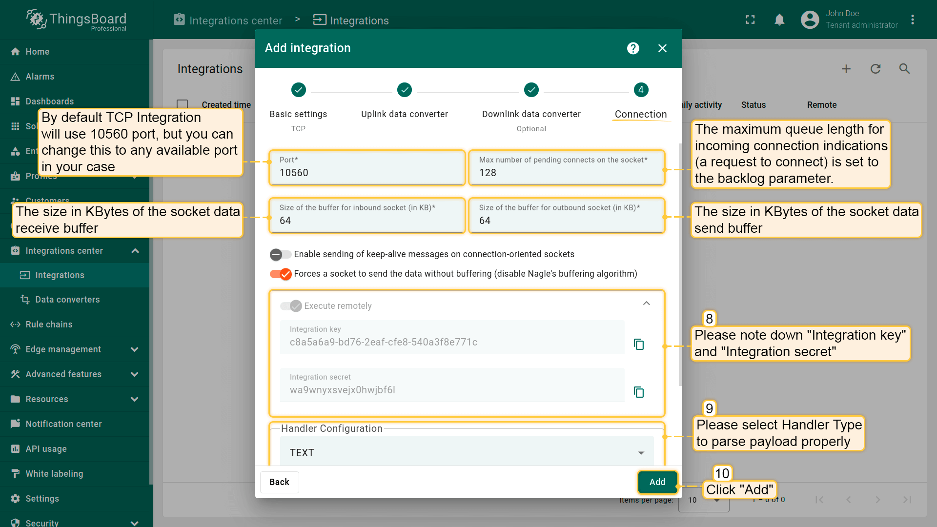
- In the “Connection” block:
- Handler Configuration: Select the device payload type from the drop-down menu.
The Execute remotely option is selected by default and cannot be changed, the TCP Integration can only be the remote type.
We keep other options by default, but there is a short description of them:
- Max number of pending connects on the socket: The maximum queue length for incoming connection indications (a request to connect) is set by the backlog parameter. If a connection indication arrives when the queue is full, the connection is denied.
- Size of the buffer for inbound socket: Specifies the size (in kilobytes) of the socket’s data receive buffer.
- Size of the buffer for outbound socket: Specifies the size (in kilobytes) of the socket’s data send buffer.
- Enable sending of keep-alive messages on connection-oriented sockets: When enabled, the socket will periodically send keep-alive probes across the network to the peer, to ensure that the connection remains active.
- Forces a socket to send the data without buffering (disable Nagle’s buffering algorithm): Disables Nagle’s algorithm on the socket, ensuring that data is sent immediately rather than waiting for a larger amount of data to accumulate.


Select the device payload type for Handler Configuration:
To parse payload properly, please make sure that next values are set:
|

|


To parse payload properly, please make sure that next values are set:
|


Modify the Edge Root Rule chain for Downlinks
We can send a downlink message to the device from the Rule chain using the rule node. To send downlink via integration, modify the Edge Root Rule chain.
Please note!
If you use earlier versions of Edge, you cannot create or edit a Rule Chain on the Edge itself. It must be configured as a template in the Cloud (Server), and then assigned to the Edge instance.
Starting with Edge version 4.0, you can create and edit a Rule Chain on the Edge.
For example, create an integration downlink node and set the ‘Attributes updated’ link to it. When changes are made to the device attribute, the downlink message is sent to the integration.


Assign Integration to Edge
Once the converter and integration templates are created, we can assign the Integration template to the Edge.
- Go to the Edge management > Instances section and click the Manage edge integrations button.
- On the Integration page, click the "Assign to edge" button. In the "Assign the Integration to the Edge" pop-up window, select the integration from the drop-down menu and click the "Assign" button.
- Login to your ThingsBoard Edge instance and go to the Integrations center > Integrations section. Confirm the TCP integration on the Edge.


Installing and running external TCP Integration
To install the remote TCP Integration service on a local or separate machine, select the appropriate platform.
Use the Integration key and Integration secret to complete the TCP Integration configuration.
To run the integration via Docker, make sure you have installed Docker CE Execute the following command to pull the image: Create a volume for the integration logs (799 is the user ID of the non-root ThingsBoard Docker user): Execute the following command to run the integration: Where:
After executing this command, you can open the logs located here: ~/.tb-pe-tcp-udp-integration-logs. You should be able to see INFO log messages containing your latest integration configuration that arrived from the server. To keep the container running in the background but detach from the session terminal, press the key sequence Ctrl+p followed by Ctrl+q. Reattaching, stop and start commandsTo reattach to the terminal (to see ThingsBoard remote integration logs), run: To stop the container: To start the container: TroubleshootingNOTE If you observe errors related to DNS issues, for example You may configure your system to use Google public DNS servers. See corresponding Linux and Mac OS instructions. |
To run the integration via Docker, make sure you have installed Docker Toolbox for Windows Windows users should use a docker-managed volume for the remote integration logs. Before executing docker, create the docker volume (for ex. tb-tcp-udp-integration-logs). Open the Docker Quickstart Terminal and run the following command: Run the integration using the following command: Where:
After executing this command, you can open the logs located here: ~/.tb-pe-tcp-udp-integration-logs. You should be able to see INFO log messages containing your latest integration configuration that arrived from the server. To keep the container running in the background but detach from the session terminal, press the key sequence Ctrl+p followed by Ctrl+q. Reattaching, stop and start commandsTo reattach to the terminal (to see ThingsBoard remote integration logs), run: To stop the container: To start the container: TroubleshootingNOTE If you observe errors related to DNS issues, for example You may configure your system to use Google public DNS servers |
Install Java 17 (OpenJDK)ThingsBoard service is running on Java 17. To install OpenJDK 17, follow these instructions Configure your operating system to use OpenJDK 17 by default. You can configure the default version by running the following command: To check the installed Java version on your system, use the following command: The expected result is: Download the installation package: Install the integration as a service: Open the file for editing: Locate the following configuration block: Enter your configuration parameters:
Make sure to uncomment the export statement. See the example below: Start the ThingsBoard integration: Advanced configurationYou can find and update additional configuration parameters in the tb-tcp-udp-integration.conf file. To open the file for editing, use the following command: After updating the configuration, you can check the logs in /var/log/tb-tcp-udp-integration/ to verify that the integration is running correctly. Look for INFO log messages that show the latest integration configuration received from the server. |
Install Java 17 (OpenJDK)ThingsBoard service is running on Java 17. Follow this instructions to install OpenJDK 17: Please don’t forget to configure your operating system to use OpenJDK 17 by default. You can configure which version is the default using the following command: You can check the installation using the following command: Expected command output is: Download the installation package: Install the integration as a service: Open the file for editing: Locate the following configuration block: Enter your configuration parameters:
Make sure to uncomment the export statement. See the example below: Start the ThingsBoard integration: Advanced configurationYou can find and update additional configuration parameters in the tb-tcp-udp-integration.conf file. To open the file for editing, use the following command: After updating the configuration, you can check the logs in /var/log/tb-tcp-udp-integration/ to verify that the integration is running correctly. Look for INFO log messages that show the latest integration configuration received from the server. |
Send uplink message
Once the ThingsBoard TCP Integration has been created, the TCP server starts, and then it waits for data from the devices.
To send the uplink message, select the device payload type:
The command to send a message to the TCP server that is running on localhost (127.0.0.1) will look like this:
We can also send multiple messages in one string, separated by Message Separator (System Line Delimiter). Newline delimiter (\n) will be used to split payload into multiple messages. In this case, the command will look like this:
|


The command to send a message to the TCP server that is running on localhost (127.0.0.1) will look like this:
|

The command to send a message to the TCP server that is running on localhost (127.0.0.1) will look like this:
|


To view the received time-series data, go to the Entities > Devices section, click the device and select the “Latest telemetry” tab:

The received data can be viewed in the Uplink converter:
- Go to the Integrations center > Data converters section and click the Uplink converter.
- On the “Data converter details” page, select the “Events” tab.
- View the message details in the “In” and “Out” columns.


Send a downlink message
To check the downlink functionality. Let’s add the firmware shared attribute:
- Go to the Entities > Devices section, click the device to open the “Device details” page.
- Select the “Attributes” tab and the “Shared attributes” scope.
- To add the firmware attribute, click the “Add” button and enter the configuration parameters.

To confirm the downlink message sent to the device, go to the Integrations center > Integrations section, click the TCP integration and select the “Events” tab:

To see the downlink response, select and send another message to the TCP integration:
|
|
|
|
An example of the message sent to the device and the response from ThingsBoard Edge in the terminal:

Next steps
-
Getting started guide - Provide quick overview of main ThingsBoard Edge features. Designed to be completed in 15-30 minutes:
-
Installation guides - Learn how to setup ThingsBoard Edge on various available operating systems and connect to ThingsBoard Server.
-
Edge Rule Engine:
-
Rule Chain Templates - Learn how to use ThingsBoard Edge Rule Chain Templates.
-
Provision Rule Chains from cloud to edge - Learn how to provision edge rule chains from cloud to edge.
-
- Security:
- gRPC over SSL/TLS - Learn how to configure gRPC over SSL/TLS for communication between edge and cloud.
-
Features:
-
Edge Status - Learn about Edge Status page on ThingsBoard Edge.
-
Cloud Events - Learn about Cloud Events page on ThingsBoard Edge.
-
-
Use cases:
-
Manage alarms and RPC requests on edge devices - This guide will show how to generate local alarms on the edge and send RPC requests to devices connected to edge:
-
Data filtering and traffic reduce - This guide will show how to send to cloud from edge only filterd amount of device data:
-
- Roadmap - ThingsBoard Edge roadmap.