Modbus
This documentation will help you set up the Modbus connector for the ThingsBoard IoT Gateway. We’ll explain the configuration parameters in simple terms to make it easy for you to understand and follow. The Modbus is a widely used protocol for industrial automation and control systems, allowing devices to communicate with each other over a network, and this connector allows seamless integration with the ThingsBoard platform. Use general configuration to enable this extension.
Also, if you are new to ThingsBoard IoT Gateway, we recommend you to read the Getting Started guide to understand the basic concepts of ThingsBoard IoT Gateway and how it works with Modbus protocol.
The connector can be configured via the user interface form, which helps you set up a connection to the Modbus server, collect data and write data to slaves (devices). Let’s look at all the available settings and explain each one clearly. This will help you understand how everything works.
Configuration modes
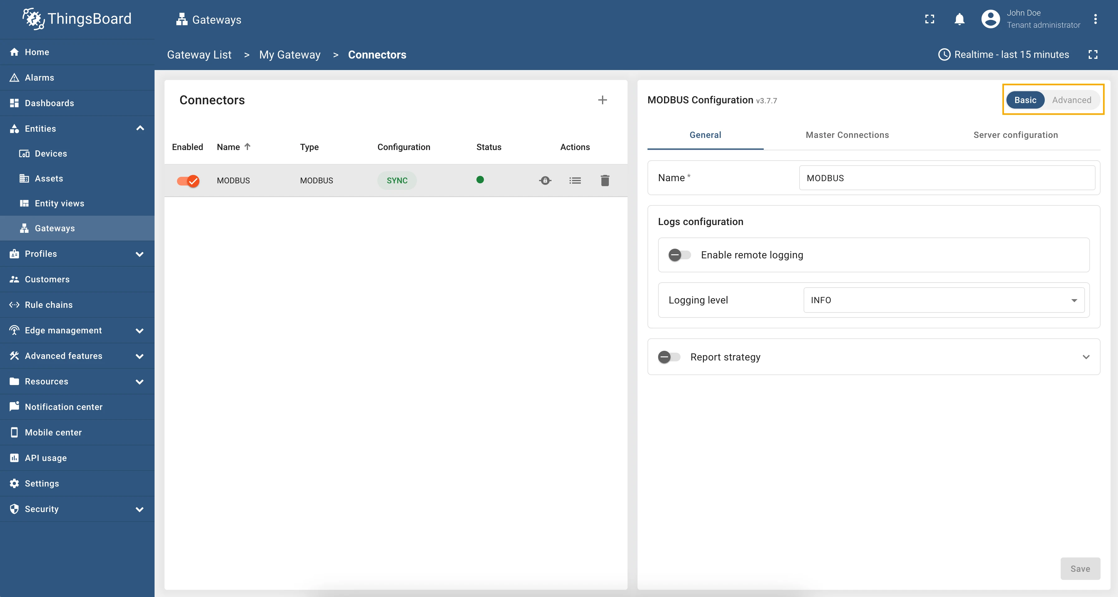
Section titled “Configuration modes”The Modbus connector can be configured in two modes: Basic and Advanced.
- Basic mode is designed for users who are new to ThingsBoard IoT Gateway and want to quickly set up the connector with minimal configuration. It provides a simplified interface with essential settings.
- Advanced mode is intended for experienced users who need more control over the configuration. It offers additional options and flexibility for advanced use cases.
You can switch between these modes using the toggle button at the top of the configuration page:
General settings
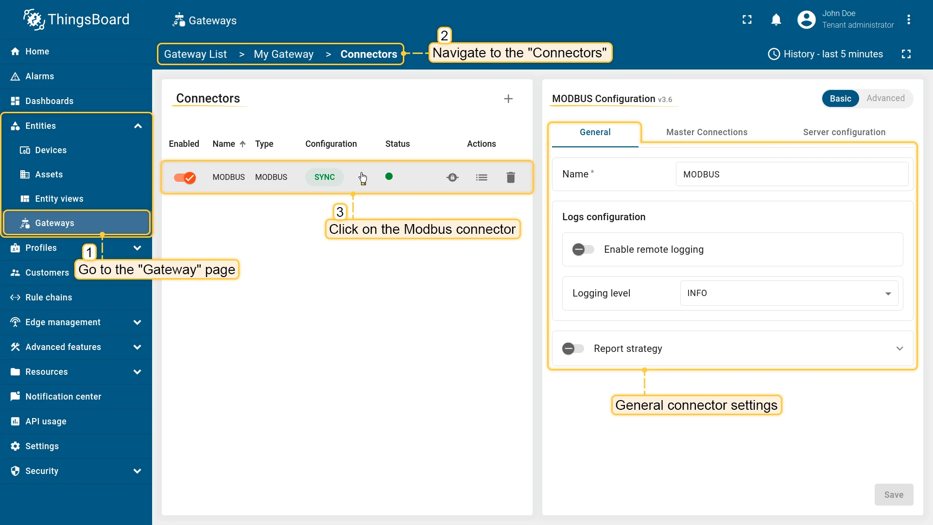
Section titled “General settings”This configuration section contains general connector settings, such as:
- Name - connector name used for logs and saving to persistent devices;
- Logs configuration - settings for local and remote logging:
- Enable remote logging - enables remote logging for the connector;
- Logging level - logging level for local and remote logs: NONE, ERROR, CRITICAL, WARNING, INFO, DEBUG, TRACE;
- Report strategy - strategy for sending data to ThingsBoard:
- Report period - period for sending data to ThingsBoard in milliseconds;
- Type - type of the report strategy:
- On report period - sends data to ThingsBoard after the report period;
- On value change - sends data to ThingsBoard when the value changes;
- On value change or report period - sends data to ThingsBoard when the value changes or after the report period;
- On received - sends data to ThingsBoard after receiving data from the device (default strategy).
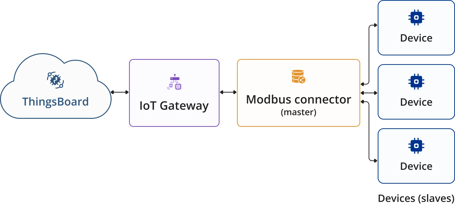
Master connections (Gateway as a Master) settings
Section titled “Master connections (Gateway as a Master) settings”A Modbus Master is used to query data from Modbus servers (slaves). In order to configure servers for data retrieving, you need to specify list of slaves.
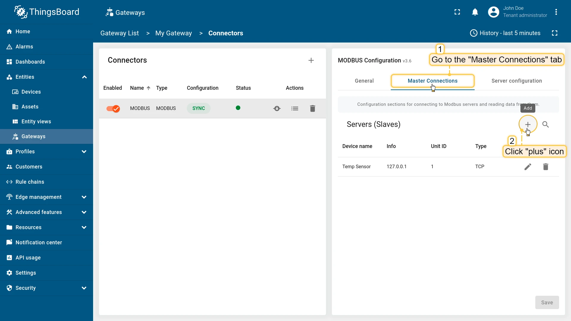
Servers (Slaves) settings
Section titled “Servers (Slaves) settings”A Modbus Slave is a device that responds to requests from a Modbus Master. In this section, you can configure the Modbus slaves that the master will query data from. You can add multiple slaves to the list, and each slave can have its own configuration.
The following parameters are used to configure the slave device, its name and profile, as well as for report strategy:
- Unit ID - ID of the Modbus slave.
- Device name - name of the device on the platform.
- Device profile - device profile name on the platform.
- Report strategy strategy for sending data to ThingsBoard:
- Report period - period for sending data to ThingsBoard in milliseconds;
- Type - type of the report strategy:
- On report period - sends data to ThingsBoard after the report period;
- On value change - sends data to ThingsBoard when the value changes;
- On value change or report period - sends data to ThingsBoard when the value changes or after the report period;
- On received - sends data to ThingsBoard after receiving data from the device (default strategy).
To add a new configuration for connection to server, navigate to the “Master Connections” tab and click the “plus” icon:
Connection settings
Section titled “Connection settings”Due to the nature of preferred way of communication between Modbus master there are 3 options how to configure this part: if using TCP, UDP or via Serial port.
The following parameters are used to configure TCP connection for the slave:
- Host - hostname or IP address of the Modbus server.
- Port - port of the Modbus server for connection.
- Method - type of a framer, either Socket or RTU.

The following parameters are used to configure UDP connection for the slave:
- Host - hostname or IP address of the Modbus server.
- Port - port of the Modbus server for connection.
- Method - type of a framer, either Socket or RTU.
The following parameters are used to configure serial connection for the slave:
- Port - port of the Modbus server for connection.
- Method - type of a framer, either ASCII or RTU.
- Baudrate - The baud rate to use for the serial device.
- Bytesize - The number of bits in a byte of serial data. This can be one of 5, 6, 7, or 8.
- Stopbits - The number of bits sent after each character in a message to indicate the end of the byte.
- Parity - The type of checksum to use to verify data integrity. This can be one of the following: (E)ven, (O)dd, (N)one.
Advanced connection settings
Section titled “Advanced connection settings”You can configure additional settings like: TLS connection, polling time, byte order and word order, and other. The table below describes the parameters for this purpose:
| Parameter | Default value | Description |
|---|---|---|
| Connection timeout (s) | 35 | Timeout in seconds for connecting to Modbus server |
| Byte order | LITTLE | Order of bytes to read |
| Word order | LITTLE | The order of words when reading several registers |
| Retries | true | Retrying sending data to the master. The values can be either: true or false |
| Retries on empty | true | Retrying sending data to the master if it is empty |
| Retries on invalid | true | Retrying sending data to the master if it is failed |
| Poll period (ms) | 5000 | Period in milliseconds to check the attributes and the telemetry on the slave |
| Connect attempt time (ms) | 5000 | A waiting period in milliseconds before connecting to the master |
| Connect attempt count | 5 | The number of connection attempts made through the ThingsBoard gateway |
| Wait after failed attempts (ms) | 300000 | A waiting period in milliseconds before trying to send data to the master |
-
Click on the “Advanced connection settings” subsection to open it;

-
Make the necessary settings.

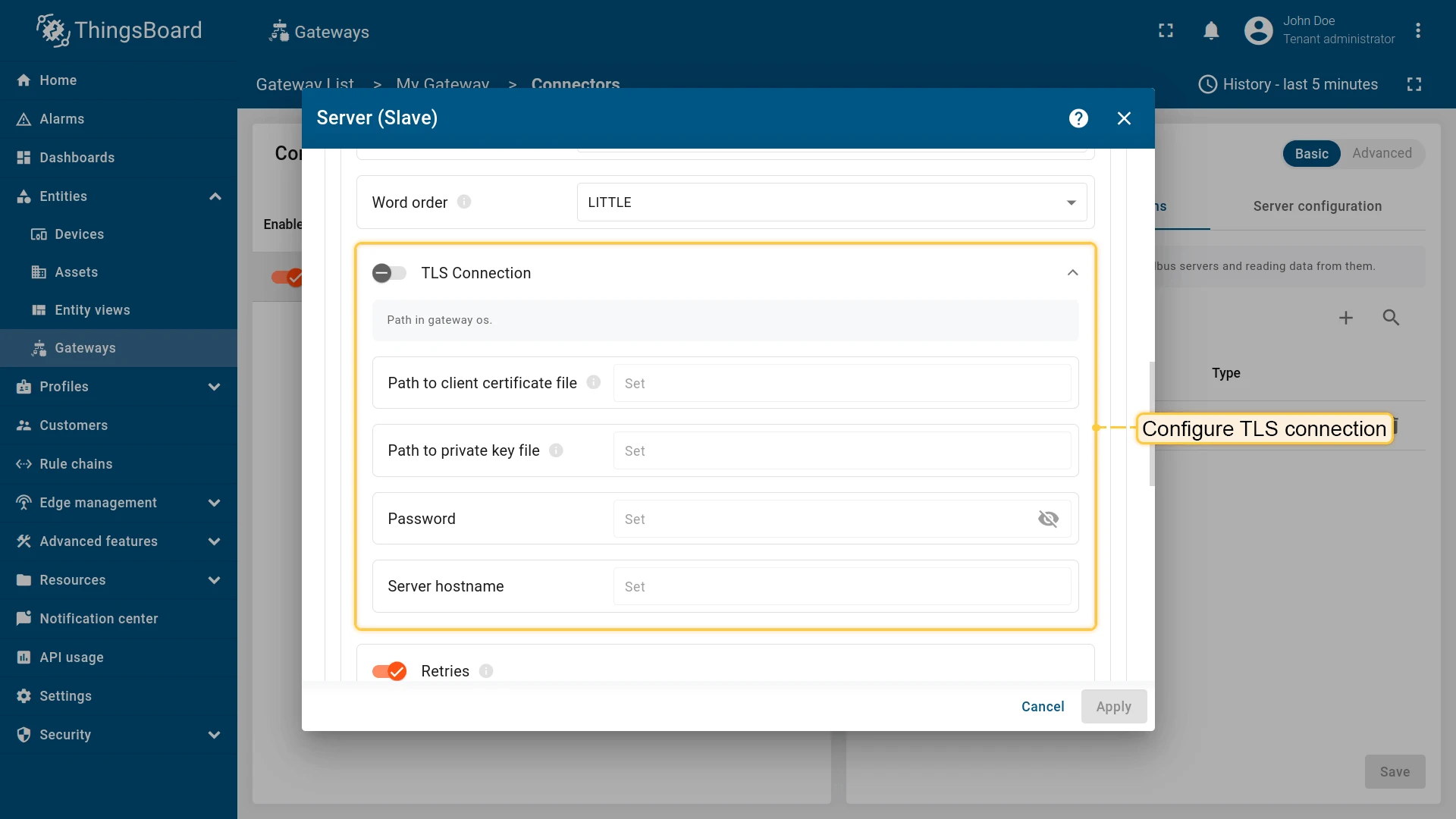
Also, you can configure TLS connection (can be used only for TCP/UDP connection type). The table below describes the parameters required to configure TLS connection:
| Parameter | Description |
|---|---|
| Path to client certificate file | Path to certificate file in filesystem with gateway |
| Path to private key file | Path to private key file |
| Password | Server password |
| Server hostname | Server hostname (Should match with hostname in certificate) |
Data mapping
Section titled “Data mapping”In the data mapping, you can specify how the Modbus master will interact with the slaves. This includes reading data from the slaves. You can also use this section to configure which data will be sent as device attributes or telemetry. Data mapping contains all the necessary settings for flexible data management.
Attributes and time series
Section titled “Attributes and time series”The configuration in this unit provides settings for processing data on Modbus server. These settings will be interpreted in ThingsBoard platform instance as attributes/time series of the device. The following parameters are used to configure device attributes and time series:
- Key - key of the attribute or time series on the platform.
- Type - data type of the Modbus register.
- Function code - Modbus function code for reading the register.
- Objects count - number of registers to read.
- Address - address of the register on the Modbus server.

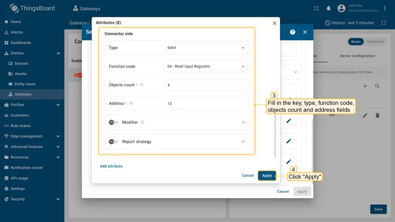
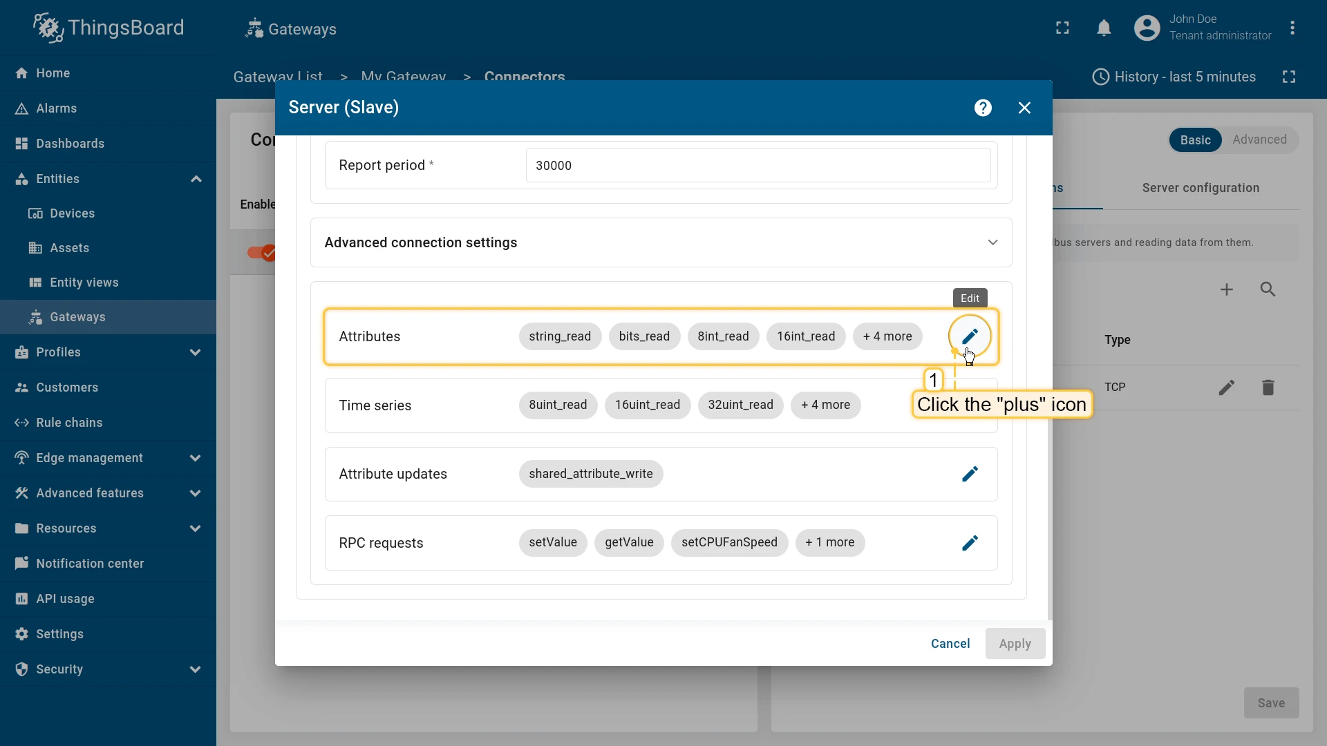
For adding a new attribute or time series, use the following steps:
-
Click on “pencil” icon in the “Attributes” or “Time series” section (depends on the selected section);
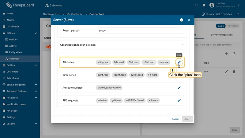
-
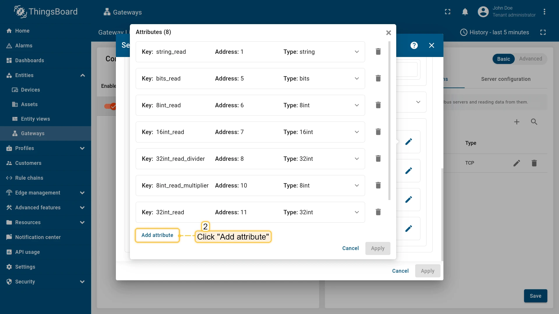
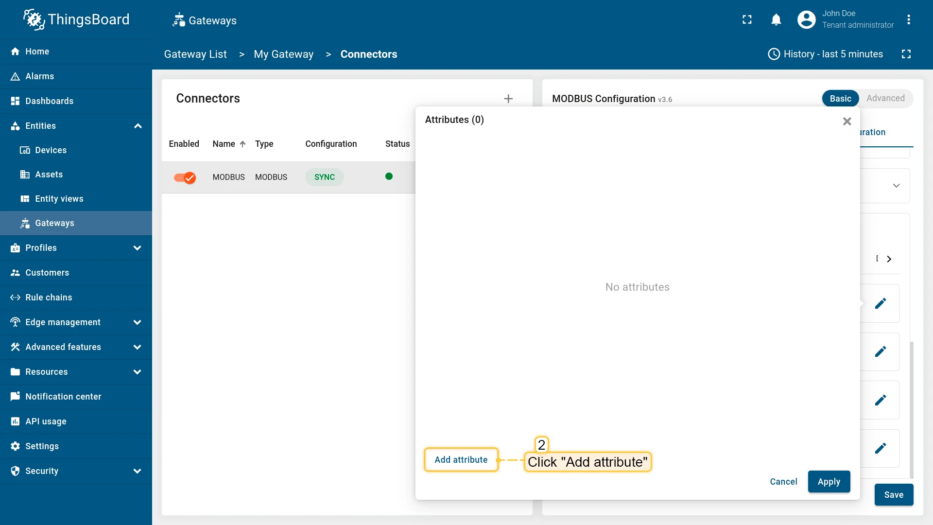
In the opened window click “Add attribute” or “Add time series” (depends on selected section);

-
Fill in key, type, function code, objects count and address fields. Click “Apply”.

Report strategy
Section titled “Report strategy”You can enable a specific report strategy for each time series or attribute. This strategy defines how often data is sent to the ThingsBoard server. The following strategies are available:
- On report period - sends data to ThingsBoard after the report period;
- On value change - sends data to ThingsBoard when the value changes;
- On value change or report period - sends data to ThingsBoard when the value changes or after the report period;
- On received - sends data to ThingsBoard after receiving data from the device (default strategy).
Enum mapping
Section titled “Enum mapping”You can map register values to human-readable strings using the enum mapping feature. This is particularly
useful for registers where value denotes a state of the device instead of a “sensor value”. Enum mapping works with
all register types. Uplink RPC to Device calls can use enum mapping to get interpreted values.
Also, enum mapping works with batch reading as expected.
In order to set up enum mapping for a specific attribute or time series, you need to define the variants parameter in the
configuration. This parameter is an object where each key represents a possible register value, and the corresponding
value is the human-readable string that describes that register value.
Example of enum mapping configuration:
{ "tag": "status", "type": "16int", "address": 1, "objectsCount": 1, "functionCode": 3, "variants": { "0": "Stopped", "1": "Booting", "2": "Running" }}Example of enum mapping configuration for coil register:
{ "tag": "relay", "type": "bits", "address": 1, "objectsCount": 1, "functionCode": 1, "bitTargetType": "int", "variants": { "0": "Disable", "1": "Enable" }}Example of enum mapping configuration for RPC to Device call:
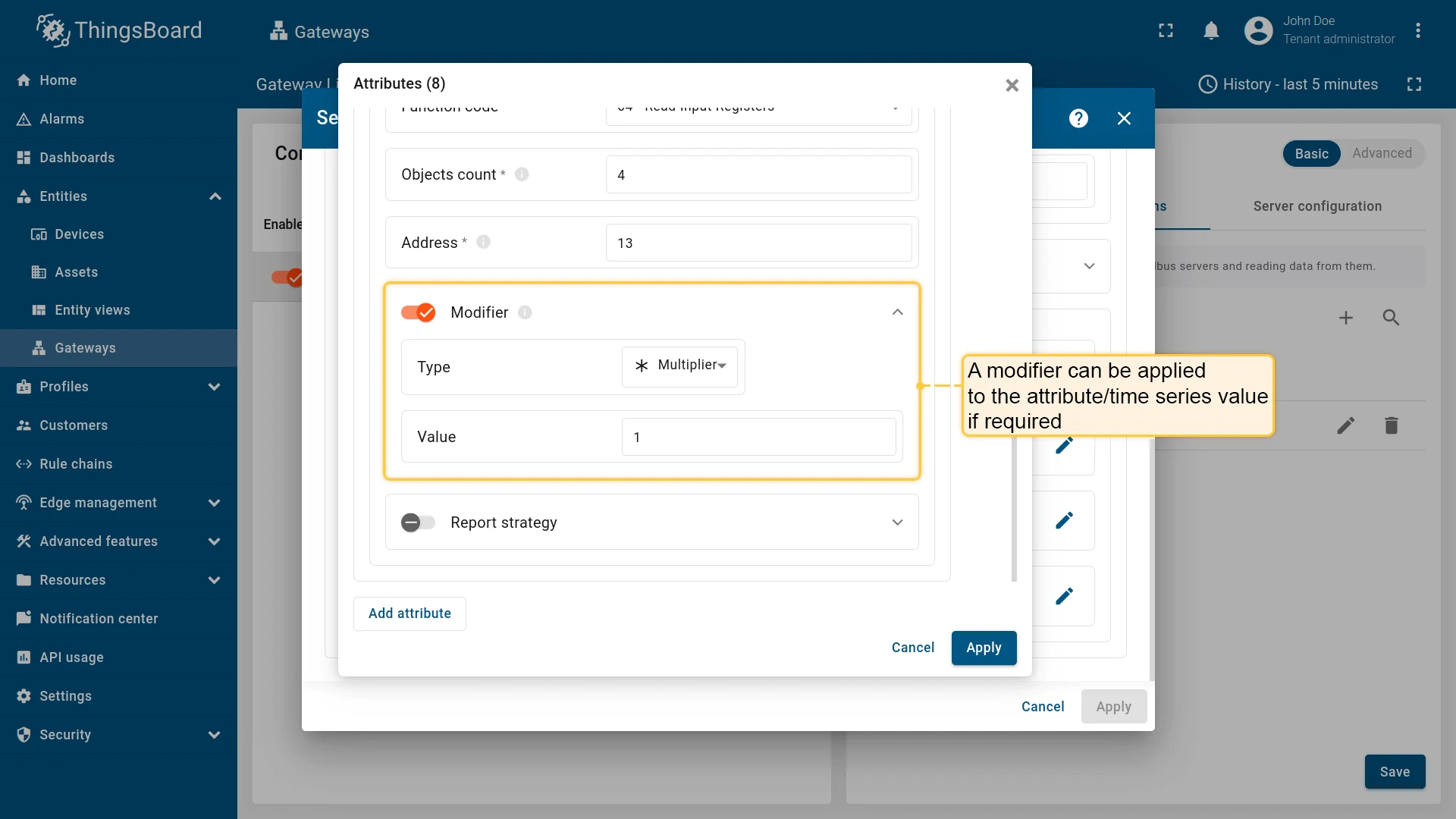
{ "method": "getStatus", "type": "16int", "address": 1, "objectsCount": 1, "functionCode": 3, "variants": { "0": "Stopped", "1": "Booting", "2": "Running" }}Modifier
Section titled “Modifier”modifier for attribute/time series value can be applied using the following settings:
| Parameter | Description |
|---|---|
| Type | multiplier - the result of reading will be multiplied by the value of this parameter. divider - the result of reading will be divided by the value of this parameter |
| Value | The value that will be used to modify the read value |
Batch reading
Section titled “Batch reading”To optimize the reading process, you can group multiple registers into a single batch read request. This approach reduces the number of requests sent to the Modbus server, which can enhance performance and decrease network traffic. Take attention that the registers in a batch read request must be of the same type and function code.
Two parameters are important for group reading configuration: address and tag. Let’s look at them in more detail:
- address - is the address of the starting register and the address of the ending register, separated by a
-character. For example,0-10means that the group read starts with the register at address0and ends at the register at address10, inclusive. - tag - is a unique identifier for each register within a group read. It is used to identify a specific register within
a given address range. The tag name can be formed using an expression using the following variables:
${address}- register address within group read.${unitId}- slave ID.${functionCode}- function code.${type}- data type of register.${objectsCount}- number of objects.
Also, divider and multiplier parameters work as expected.
Example of group reading configuration:
{ "tag": "${unitId} - ${type} - ${address}", "type": "16int", "functionCode": 3, "objectsCount": 1, "address": "0-10"}Usage examples
Section titled “Usage examples”As an example, we will use ThingsBoard Modbus Demo Server, which can be run using Docker and the following command:
docker run -it -p 5021:5021 thingsboard/tb-gw-modbus-server:latestThe server available at 0.0.0.0:5021. The server has the following structure:
| Variable Name | Register Type | Data Type | Address |
|---|---|---|---|
| Temperature | Holding | 16int | 0 |
| Humidity | Holding | 16int | 1 |
| Power | Holding | 16int | 2 |
| Pressure | Holding | 16int | 3 |
| Relay | Coil | bits | 1 |
We are interested in register 1, which contains the relay state value (off/on).
To read the value of this register, we need to add this register as attribute/telemetry in the device configuration.
To do this, follow these steps:
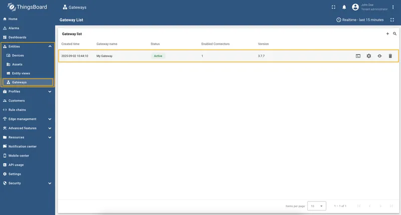
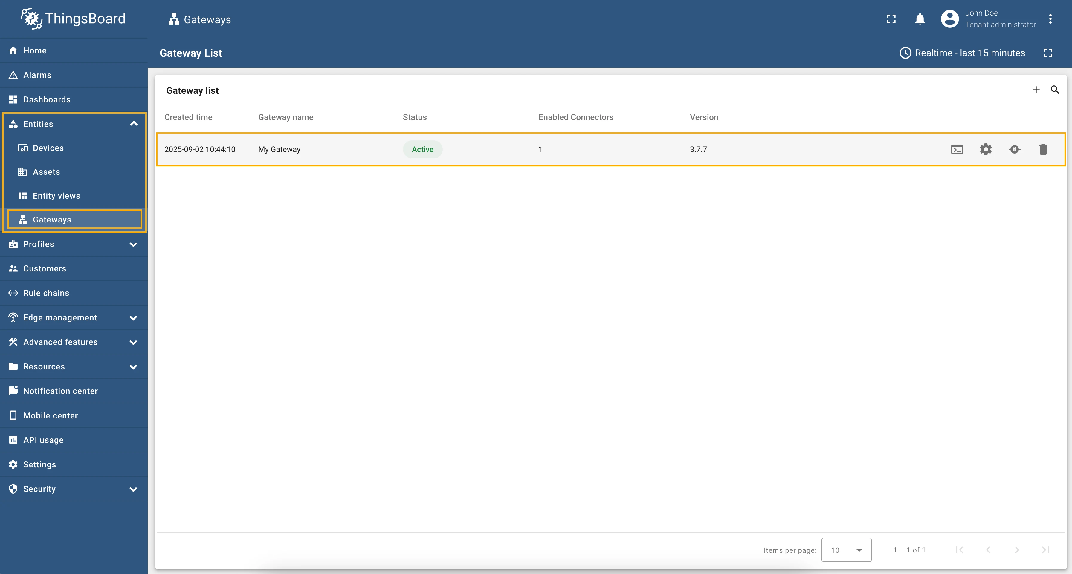
-
Go to “Entities” → “Gateways” in the left sidebar and select your gateway.
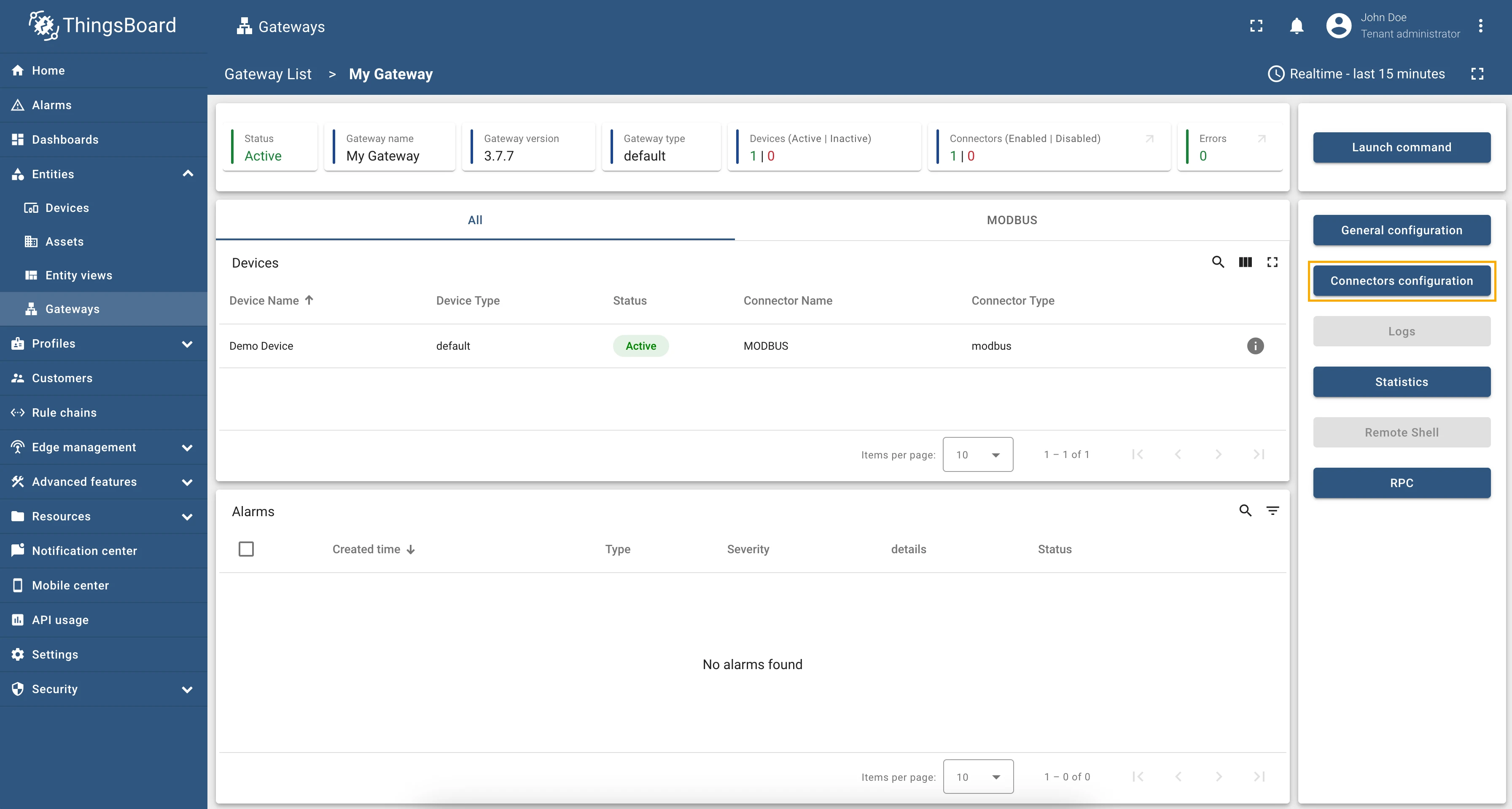
-
Click on the “Connectors configuration” button on the right side menu.

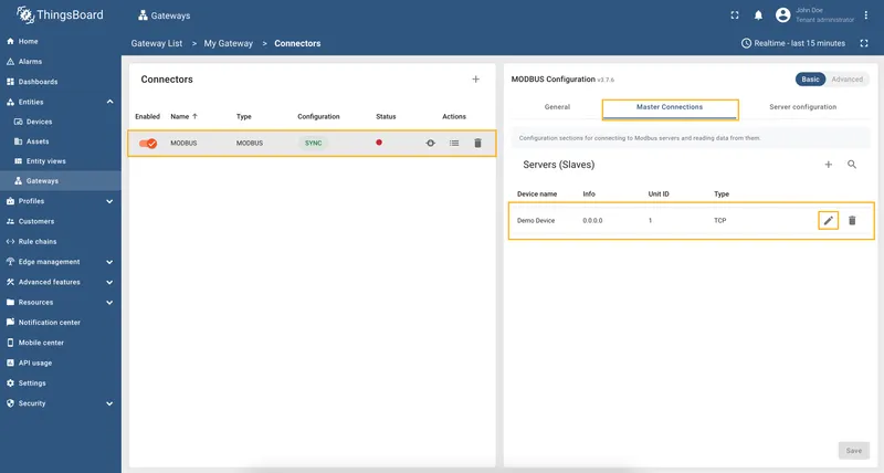
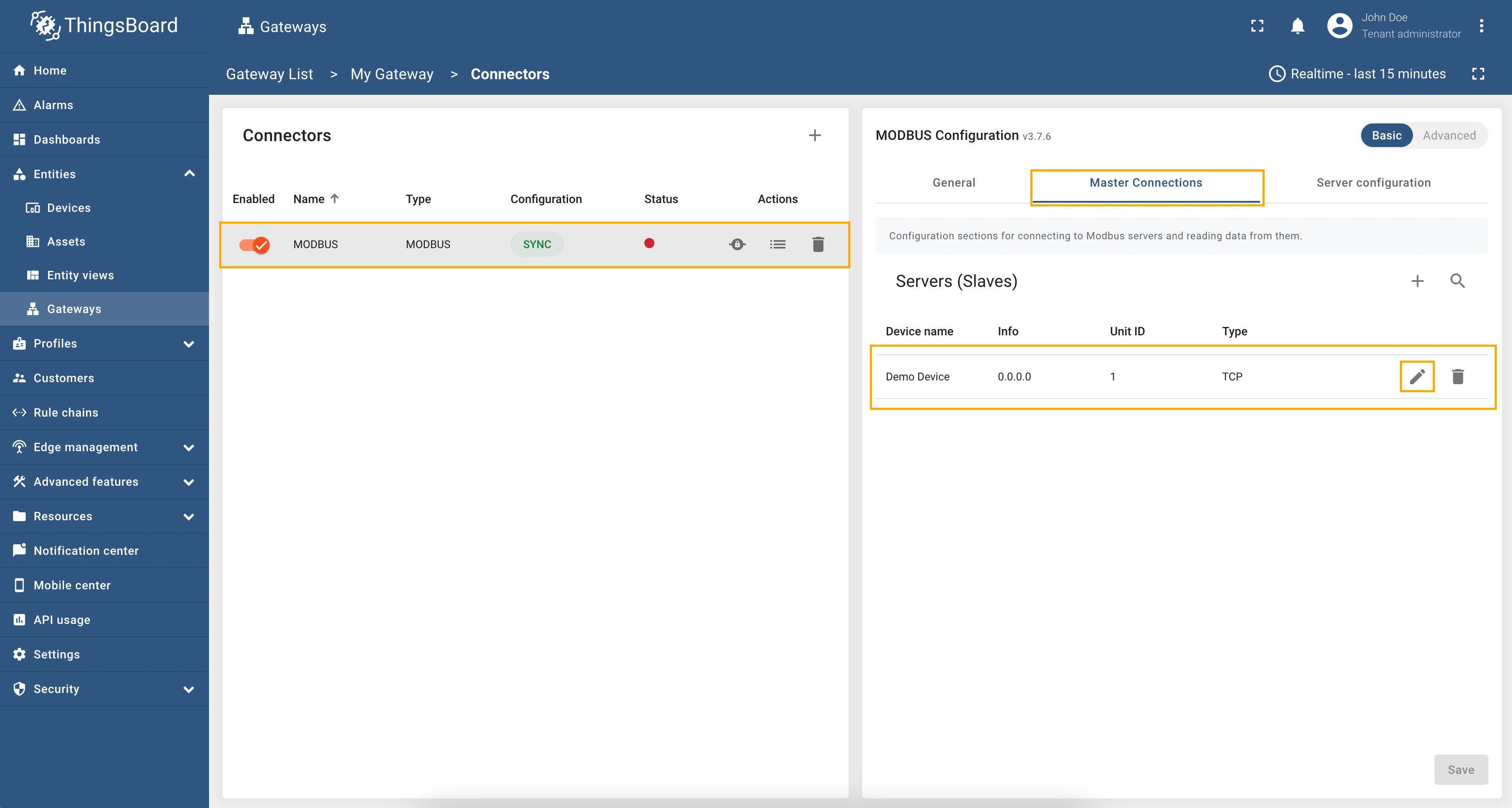
-
Select the created Modbus connector and click on the “Master Connections” tab. Make sure you have configured and connected device (if you don’t know how to do it, see Getting Started guide or Connection settings and Data mapping sections of this guide). Click on the “Pencil” icon on a device you want to configure attribute updates for.
-
Scroll down to the “Attributes or Time series” section and click on the “Pencil” icon to edit the attributes and telemetry.

-
Click on the “Add attribute” or “Add telemetry” button. In our case, we will add
relaytime series, so fill in the “Key” field withrelay, select the “Type” as bits, select “Function code” field as “01 - Read Coils”, select “Bit target type” as “Boolean”, and in the “Address” field enter1. This is the address of the Modbus register we want to read.
-
Remember to save your changes by clicking the “Apply” button.


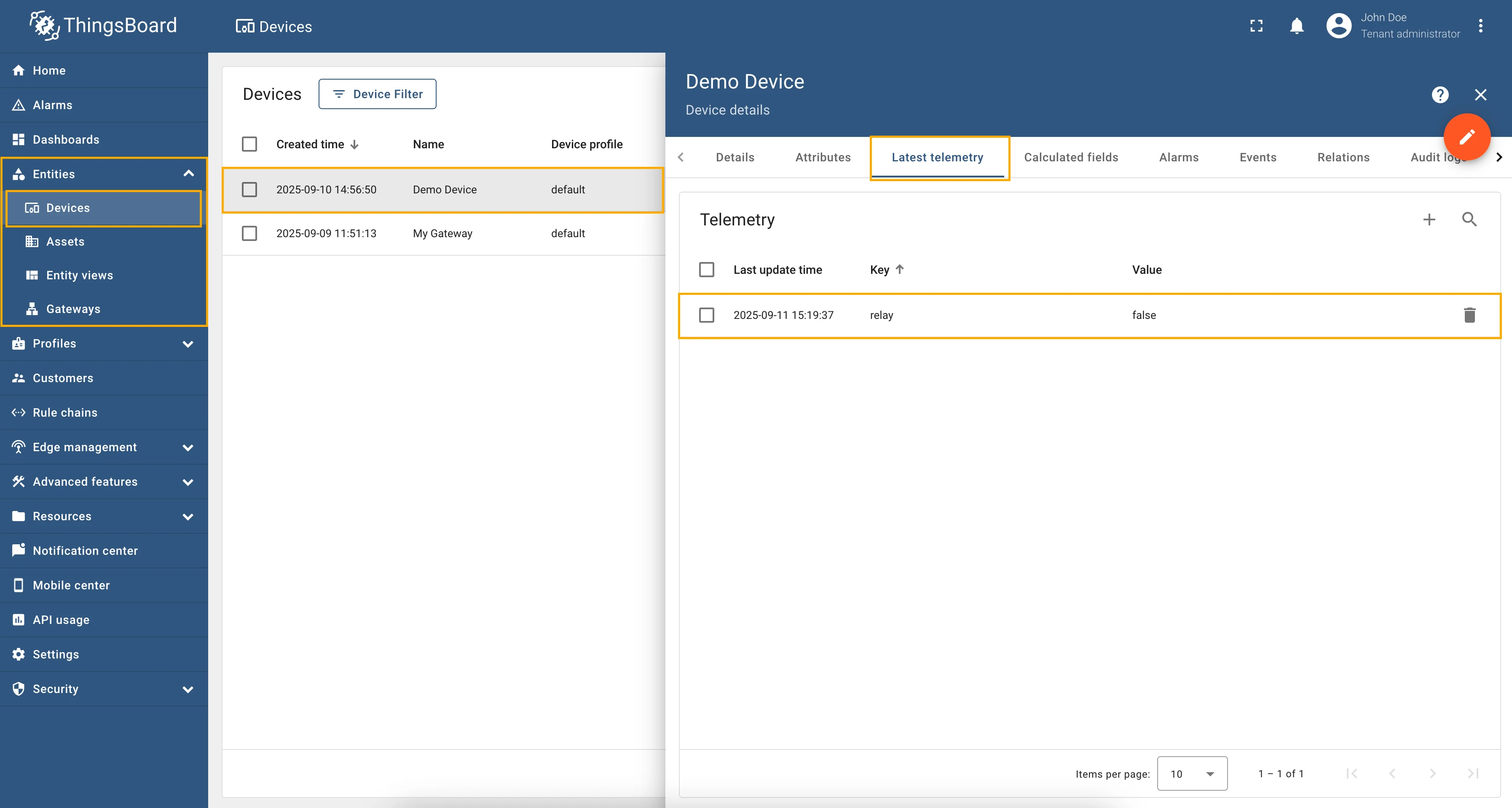
Now we can check if the attribute/telemetry works. Go to “Entities” → “Devices” → select a created
device → “Last telemetry” tab and check the value of the relay telemetry. It should be false since the
default value of the relay is off.
Full configuration for Modbus connector for the example above will look like this:
{ "master": { "slaves": [ { "host": "0.0.0.0", "port": 5021, "method": "socket", "unitId": 1, "deviceName": "Demo Device", "deviceType": "default", "timeout": 35, "byteOrder": "LITTLE", "wordOrder": "LITTLE", "retries": true, "retryOnEmpty": true, "retryOnInvalid": true, "pollPeriod": 1000, "connectAttemptTimeMs": 500, "connectAttemptCount": 5, "waitAfterFailedAttemptsMs": 30000, "type": "tcp", "attributes": [], "timeseries": [ { "tag": "relay", "type": "bits", "address": 1, "objectsCount": 1, "functionCode": 1, "bitTargetType": "bool" } ], "attributeUpdates": [], "rpc": [] } ] }}As an example, we will use ThingsBoard Modbus Demo Server, which can be run using Docker and the following command:
docker run -it -p 5021:5021 thingsboard/tb-gw-modbus-server:latestThe server available at 0.0.0.0:5021. The server has the following structure:
| Variable Name | Register Type | Data Type | Address |
|---|---|---|---|
| Temperature | Holding | 16int | 0 |
| Humidity | Holding | 16int | 1 |
| Power | Holding | 16int | 2 |
| Pressure | Holding | 16int | 3 |
| Relay | Coil | bits | 1 |
A fairly common practice when using Modbus devices is when the values we get from registers need to be multiplied by a
certain number to get the correct value. For example, if we read the power from a register and the value in
the register is 2534, and we need to get 253400 watts, then we need to multiply the value by 100.
To implement this in the device configuration, we can use the “Multiplier” field in the attributes and telemetry settings.
To read the register value with a multiplier, follow these steps:
-
Go to “Entities” → “Gateways” in the left sidebar and select your gateway.
-
Click on the “Connectors configuration” button on the right side menu.
-
Select the created Modbus connector and click on the “Master Connections” tab. Make sure you have configured and connected device (if you don’t know how to do it, see Getting Started guide or Connection settings and Data mapping sections of this guide). Click on the “Pencil” icon on a device you want to configure attribute updates for.
-
Scroll down to the “Attributes or Time series” section and click on the “Pencil” icon to edit the attributes and telemetry.
-
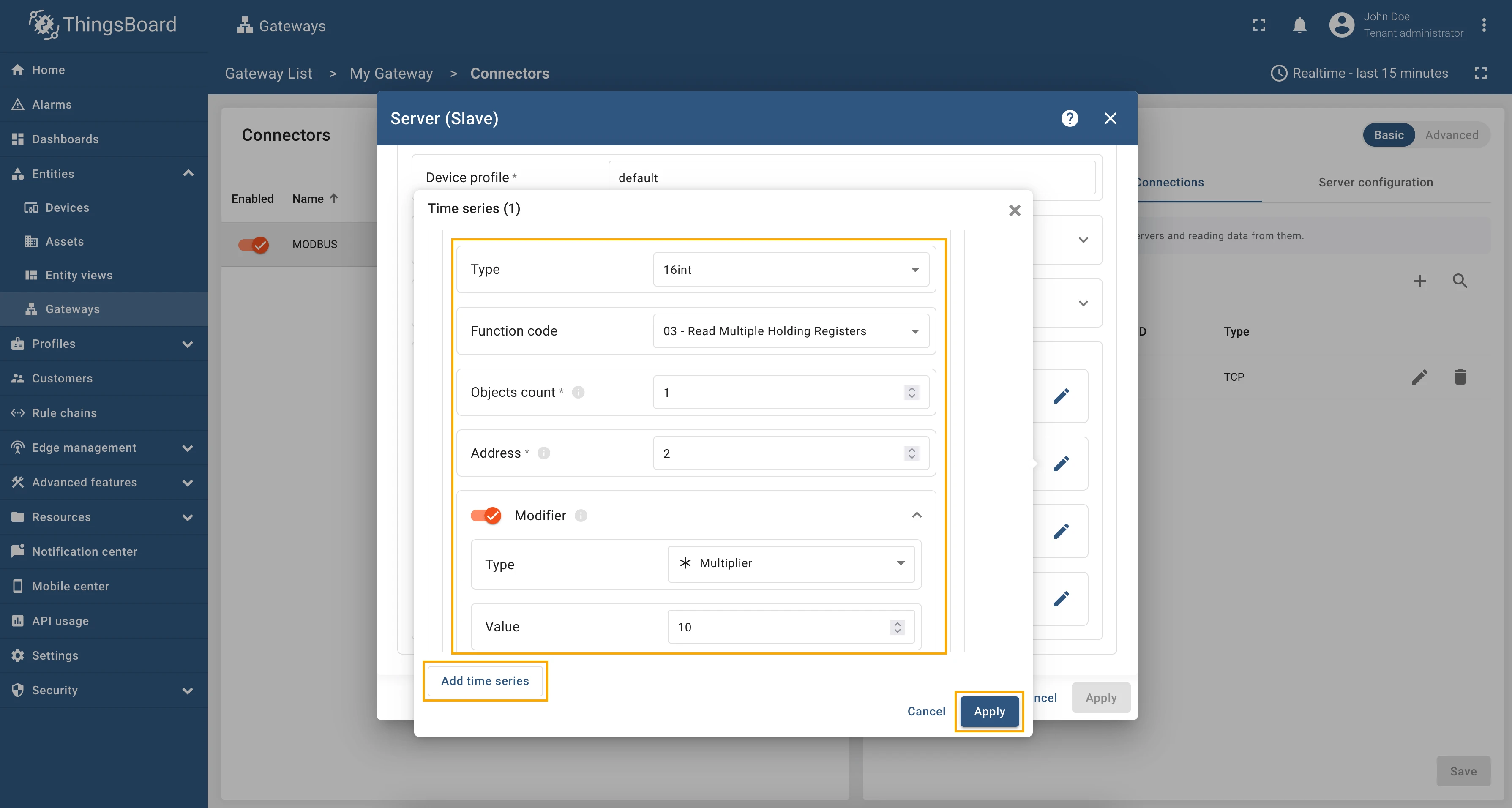
Click on the “Add attribute” or “Add telemetry” button. In our case, we will add
powertime series, so fill in the “Key” field withpower, select the “Type” as 16int, select “Function code” field as “03 - Read Holding Registers”, in the “Address” field enter2, enable “Modifier” toggle, select “Multiplier” as “Type” and enter10in “Value” field.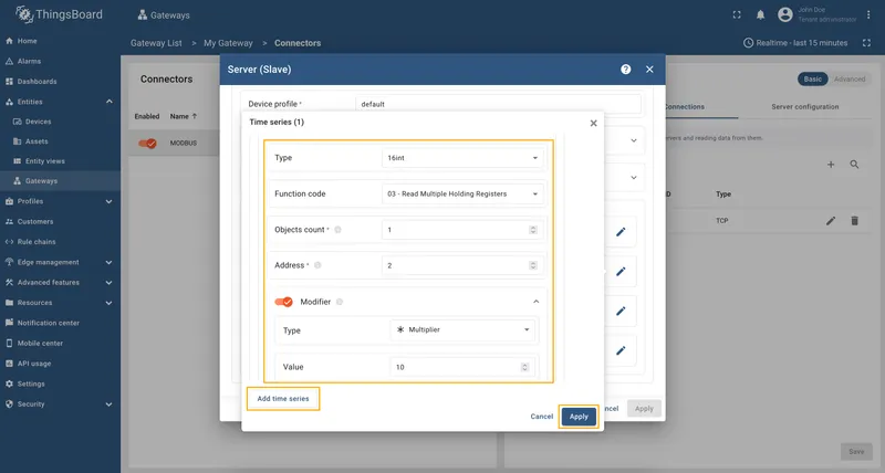
-
Remember to save your changes by clicking the “Apply” button.


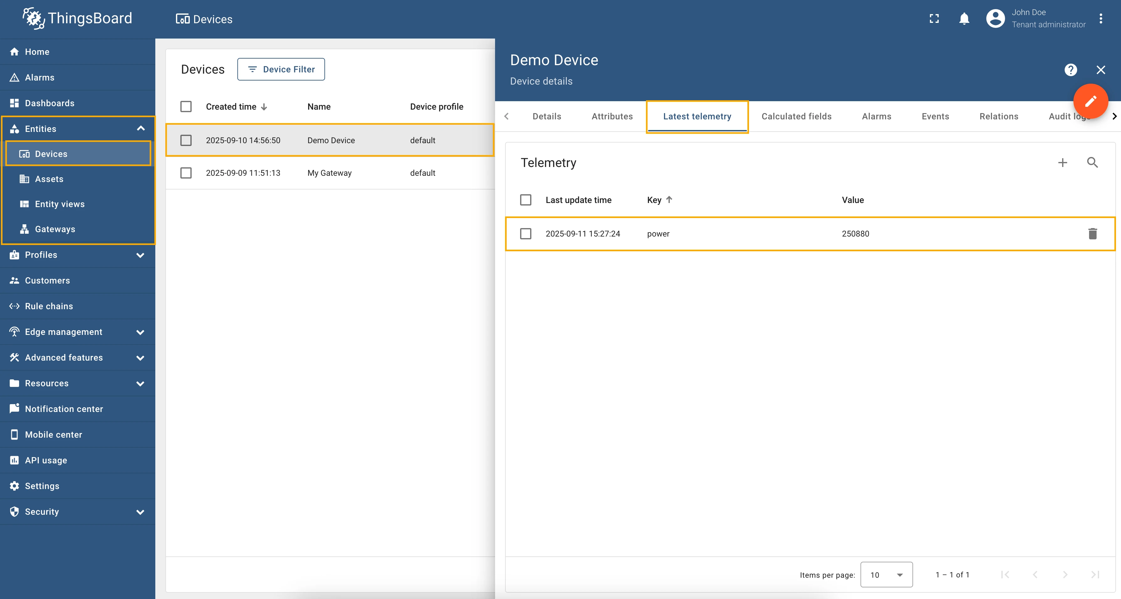
Now we can check if the telemetry with the multiplier works. Go to “Entities” → “Devices” → select a created
device → “Last telemetry” tab and check the value of the power telemetry.
Full configuration for Modbus connector for the example above will look like this:
{ "master": { "slaves": [ { "host": "0.0.0.0", "port": 5021, "method": "socket", "unitId": 1, "deviceName": "Demo Device", "deviceType": "default", "timeout": 35, "byteOrder": "LITTLE", "wordOrder": "LITTLE", "retries": true, "retryOnEmpty": true, "retryOnInvalid": true, "pollPeriod": 1000, "connectAttemptTimeMs": 500, "connectAttemptCount": 5, "waitAfterFailedAttemptsMs": 30000, "type": "tcp", "attributes": [], "timeseries": [ { "tag": "power", "type": "16int", "address": 2, "objectsCount": 1, "functionCode": 3, "multiplier": 10 } ], "attributeUpdates": [], "rpc": [] } ] }}As an example, we will use ThingsBoard Modbus Demo Server, which can be run using Docker and the following command:
docker run -it -p 5021:5021 thingsboard/tb-gw-modbus-server:latestThe server available at 0.0.0.0:5021. The server has the following structure:
| Variable Name | Register Type | Data Type | Address |
|---|---|---|---|
| Temperature | Holding | 16int | 0 |
| Humidity | Holding | 16int | 1 |
| Power | Holding | 16int | 2 |
| Pressure | Holding | 16int | 3 |
| Relay | Coil | bits | 1 |
A fairly common practice when using Modbus devices is when the values we get from registers need to be divided by a
certain number to get the correct value. For example, if we read the temperature from a register and the value in
the register is 2534, and we need to get 25.34 degrees, then we need to divide the value by 100.
To implement this in the device configuration, we can use the “Divider” field in the attributes and telemetry settings.
To read the register value with a divider, follow these steps:
-
Go to “Entities” → “Gateways” in the left sidebar and select your gateway.
-
Click on the “Connectors configuration” button on the right side menu.
-
Select the created Modbus connector and click on the “Master Connections” tab. Make sure you have configured and connected device (if you don’t know how to do it, see Getting Started guide or Connection settings and Data mapping sections of this guide). Click on the “Pencil” icon on a device you want to configure attribute updates for.
-
Scroll down to the “Attributes or Time series” section and click on the “Pencil” icon to edit the attributes and telemetry.
-
Click on the “Add attribute” or “Add telemetry” button. In our case, we will add
temperaturetime series, so fill in the “Key” field withtemperature, select the “Type” as 16int, select “Function code” field as “03 - Read Holding Registers”, in the “Address” field enter0, enable “Modifier” toggle, select “Divider” as “Type” and enter10in “Value” field.
-
Remember to save your changes by clicking the “Apply” button.


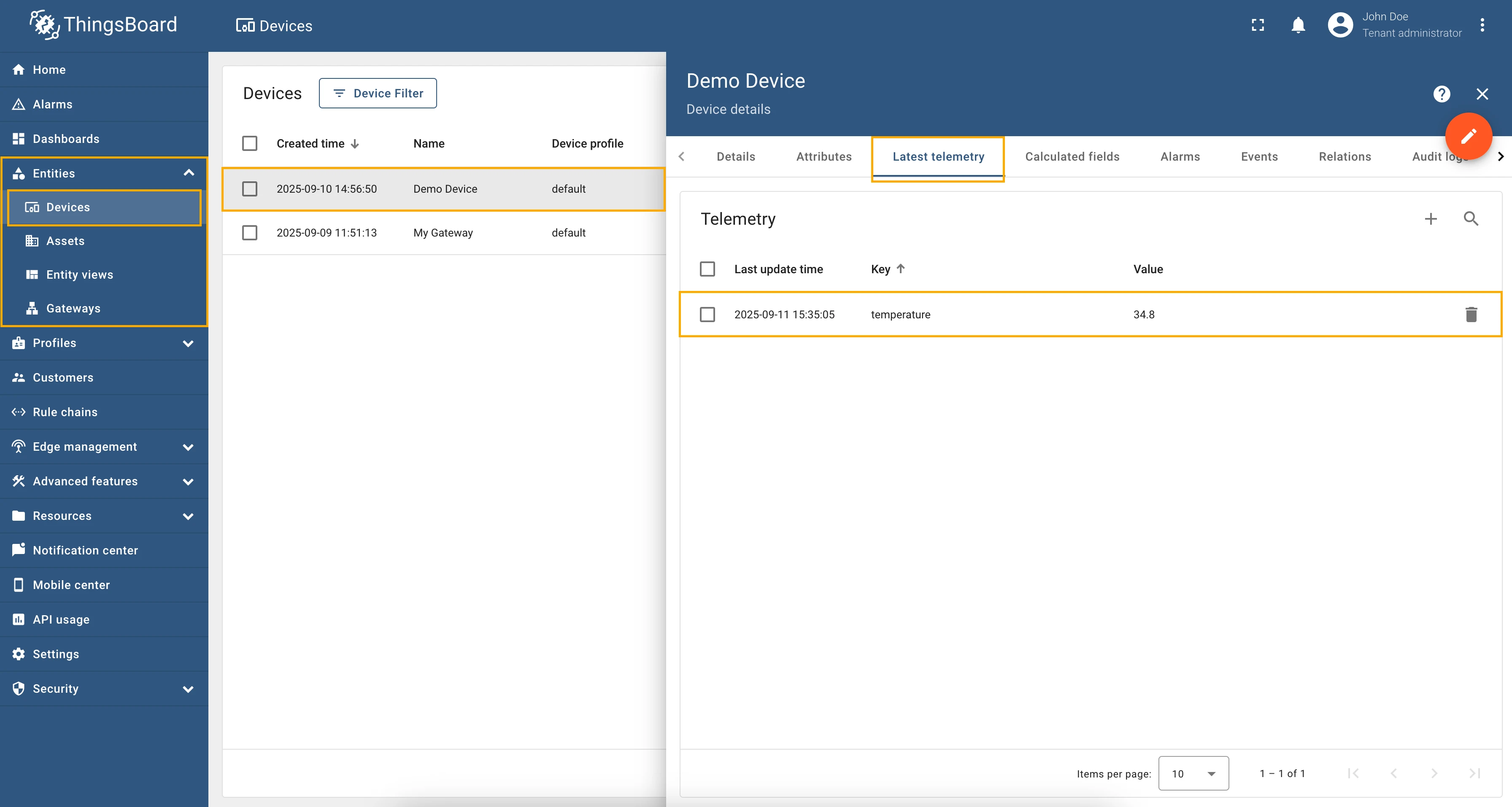
Now we can check if the telemetry with the divider works. Go to “Entities” → “Devices” → select a created
device → “Last telemetry” tab and check the value of the temperature telemetry.
Full configuration for Modbus connector for the example above will look like this:
{ "master": { "slaves": [ { "host": "0.0.0.0", "port": 5021, "method": "socket", "unitId": 1, "deviceName": "Demo Device", "deviceType": "default", "timeout": 35, "byteOrder": "BIG", "wordOrder": "LITTLE", "retries": true, "retryOnEmpty": true, "retryOnInvalid": true, "pollPeriod": 1000, "connectAttemptTimeMs": 500, "connectAttemptCount": 5, "waitAfterFailedAttemptsMs": 30000, "type": "tcp", "attributes": [], "timeseries": [ { "tag": "temperature", "type": "16int", "address": 0, "objectsCount": 1, "functionCode": 3, "divider": 10 } ], "attributeUpdates": [], "rpc": [] } ] }}Can be configured in advanced configuration mode only.
As an example, we will use ThingsBoard Modbus Demo Server, which can be run using Docker and the following command:
docker run -it -p 5021:5021 thingsboard/tb-gw-modbus-server:latestThe server available at 0.0.0.0:5021. The server has the following structure:
| Variable Name | Register Type | Data Type | Address |
|---|---|---|---|
| Temperature | Holding | 16int | 0 |
| Humidity | Holding | 16int | 1 |
| Power | Holding | 16int | 2 |
| Pressure | Holding | 16int | 3 |
| Relay | Coil | bits | 1 |
For optimizing the number of requests sent to the Modbus server, you can use the Batch reading feature available in the advanced configuration mode. This feature allows reading multiple registers in a single request, which can significantly reduce the load on the Modbus server and improve performance.
Let’s look at an example of how to properly configure batch reading to read the temperature, humidity, power,
and pressure registers from the Modbus server.
From the table above, we can see that all the required registers are of the same type (16int) and have the same
function code (03 - Read Holding Registers). This means that we can group them into a single batch read request.
We need to read registers from address 0 to address 3, so our address range will be 0-3.
Also, you need to use, for examples ${address} variable in the tag field to uniquely identify each register within
the batch read. In our case, we will use the following expression for the tag field:
${unitId}.${type}.${address} (you can find more information about variables in the corresponding section of
the documentation).
Copy and paste the following configuration into the Modbus connector advanced configuration mode:
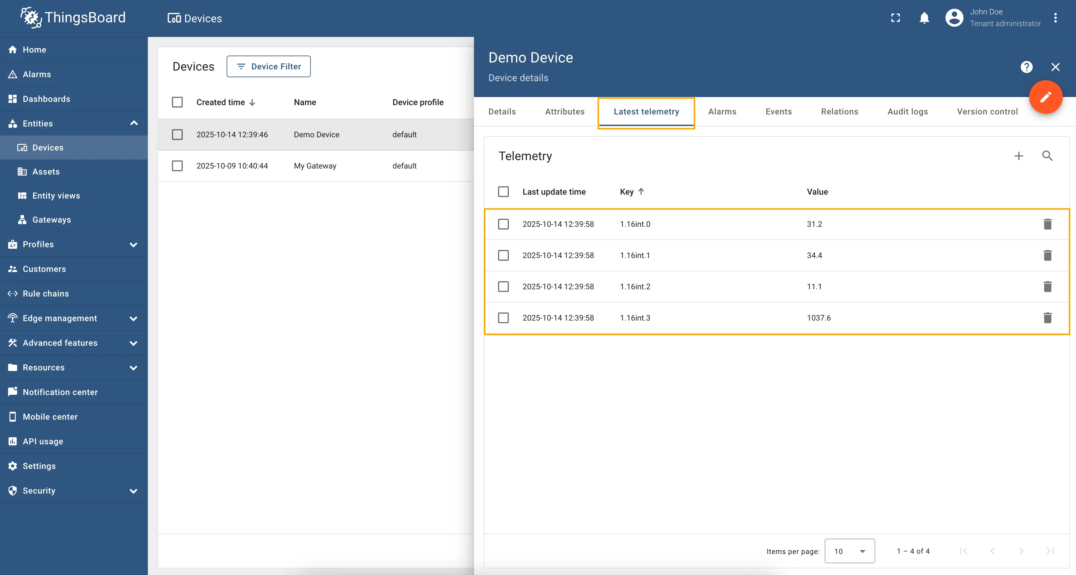
{ "master": { "slaves": [ { "host": "0.0.0.0", "port": 5021, "type": "tcp", "method": "socket", "timeout": 35, "byteOrder": "BIG", "wordOrder": "LITTLE", "retries": true, "retryOnEmpty": true, "retryOnInvalid": true, "pollPeriod": 1000, "unitId": 1, "deviceName": "Demo Device", "deviceType": "default", "sendDataOnlyOnChange": true, "connectAttemptTimeMs": 5000, "connectAttemptCount": 5, "waitAfterFailedAttemptsMs": 300000, "attributes": [], "timeseries": [ { "tag": "${unitId}.${type}.${address}", "type": "16int", "functionCode": 3, "objectsCount": 1, "address": "0-3", "divider": 10 } ], "attributeUpdates": [], "rpc": [] } ] }}After saving the changes and starting the connector, you see that the corresponding telemetry is being updated correctly:
Can be configured in advanced configuration mode only.
Modbus devices can have registers that represent enumerated values, for example operational modes, status codes, or error states. To make these values more understandable, you can map them to human-readable strings using the enum mapping feature in ThingsBoard IoT Gateway Modbus connector. This feature works for all register types and can be used in both uplink data (attributes and time series) and uplink RPC to Device calls. Let’s explore how to set up enum mapping in your Modbus connector configuration.
As an example, we will use ThingsBoard Modbus Demo Server, which can be run using Docker and the following command:
docker run -it -p 5021:5021 thingsboard/tb-gw-modbus-server:latestThe server available at 0.0.0.0:5021. The server has the following structure:
| Variable Name | Register Type | Data Type | Address |
|---|---|---|---|
| Temperature | Holding | 16int | 0 |
| Humidity | Holding | 16int | 1 |
| Power | Holding | 16int | 2 |
| Pressure | Holding | 16int | 3 |
| Operational Mode | Holding | 16int | 4 |
| Relay | Coil | bits | 1 |
We are interested in mapping the Operational Mode and Relay registers to human-readable strings. The Operational Mode register can have the following values:
1: Normal Mode2: Service Mode3: Calibration Mode
And the Relay register can have the following values:
0: OFF1: ON
To set up enum mapping for these registers, you need to define the variants parameter in the configuration for each
register. This parameter is an object where each key represents a possible register value, and the corresponding value
is the human-readable string that describes that register value.
Copy and paste the following configuration into the Modbus connector advanced configuration mode:
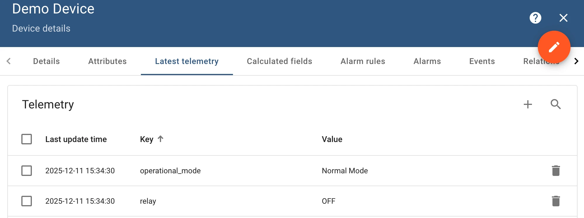
{ "master": { "slaves": [ { "host": "0.0.0.0", "port": 5021, "method": "socket", "unitId": 1, "deviceName": "Demo Device", "deviceType": "default", "timeout": 35, "byteOrder": "BIG", "wordOrder": "BIG", "retries": true, "retryOnEmpty": true, "retryOnInvalid": true, "pollPeriod": 1000, "connectAttemptTimeMs": 500, "connectAttemptCount": 5, "waitAfterFailedAttemptsMs": 1000, "type": "tcp", "attributes": [], "timeseries": [ { "tag": "operational_mode", "type": "16int", "address": 4, "objectsCount": 1, "functionCode": 3, "variants": { "1": "Normal Mode", "2": "Service Mode", "3": "Calibration Mode" } }, { "tag": "relay", "type": "bits", "address": 1, "objectsCount": 1, "functionCode": 1, "bitTargetType": "int", "variants": { "0": "OFF", "1": "ON" } } ], "attributeUpdates": [], "rpc": [] } ] }}After applying this configuration, the operational_mode and relay registers will be mapped to their respective
human-readable strings in uplink data. This makes it easier to interpret the data received from the Modbus device:
Requests mapping
Section titled “Requests mapping”The Requests mapping section allows you to configure how the ThingsBoard platform instance will interact with the devices. That is, how the platform will request data from the devices, how it will update device attributes, and how it will send RPC commands to the devices.
Modbus connector supports the following requests mapping:
- Attribute updates - allows update device nodes values from ThingsBoard platform instance.
- RPC methods - allows sending RPC commands to devices. Using RPC methods, you can get or set values of the Modbus
registers. Modbus connector supports different types of RPC methods, such as:
- Reserved GET/SET methods - these methods are automatically created for each attribute and time series parameter. You can use them to get or set values of the Modbus registers.
- Configurable RPC methods to device - these methods allow you to configure custom RPC commands in connector configuration that can be sent to the devices.
Subsection “Attribute updates”
Section titled “Subsection “Attribute updates””This subsection contains configuration for attribute updates request from ThingsBoard platform instance.
ThingsBoard allows provisioning device attributes and fetches some of them from the device application. You can treat this as a remote configuration for devices. Your devices are able to request shared attributes from ThingsBoard. See user guide for more details.
The following parameters are used to configure attribute updates:
- Key - shared attribute name.
- Type - type of value, which is used to identify the data type of the value that is being received.
- Function code - function to use for data processing, specifically Modbus functions.
- Objects count - count of objects to write or read, which specifies how many registers will be processed in the request.
- Address - object address, which is used to identify the specific object in the Modbus protocol.
In order to add new attribute update, follow these steps:
-
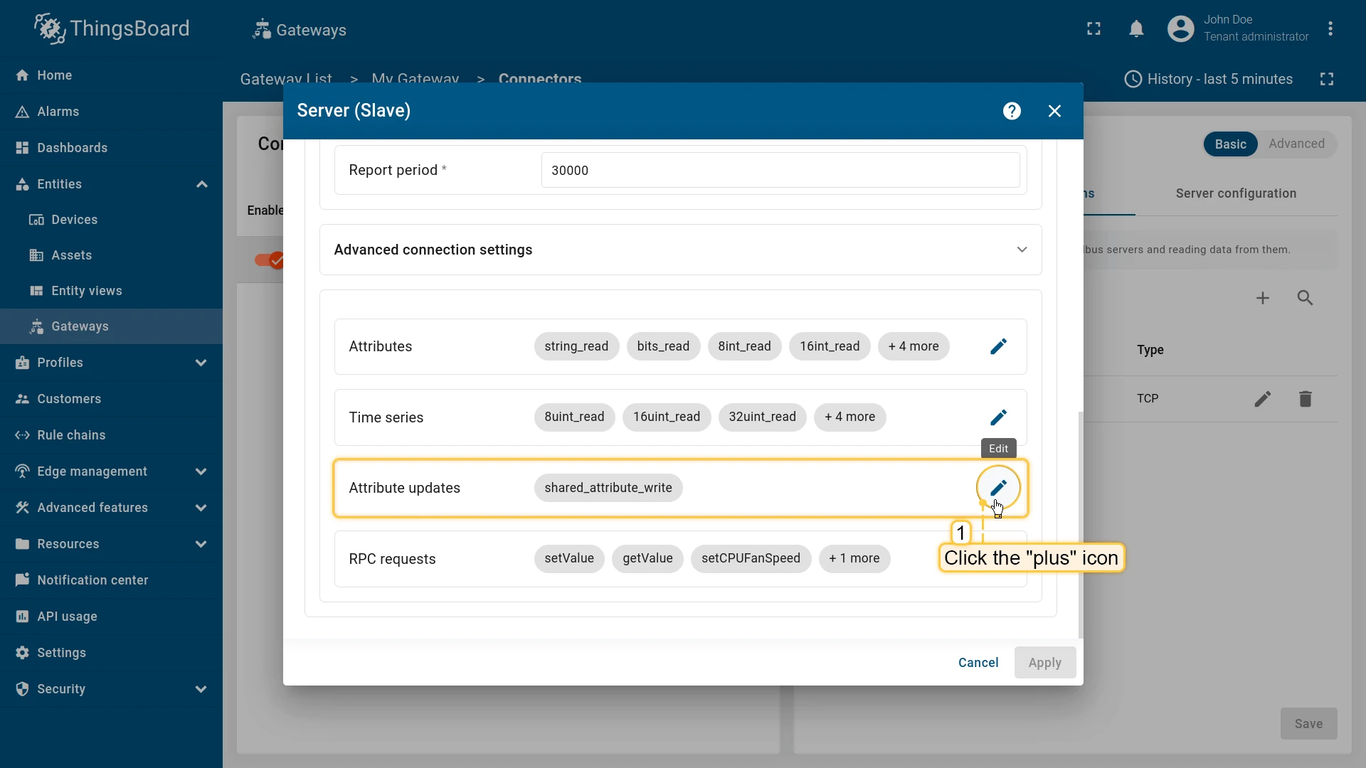
Navigate to the “Attribute updates” section and click the “pencil” icon;

-
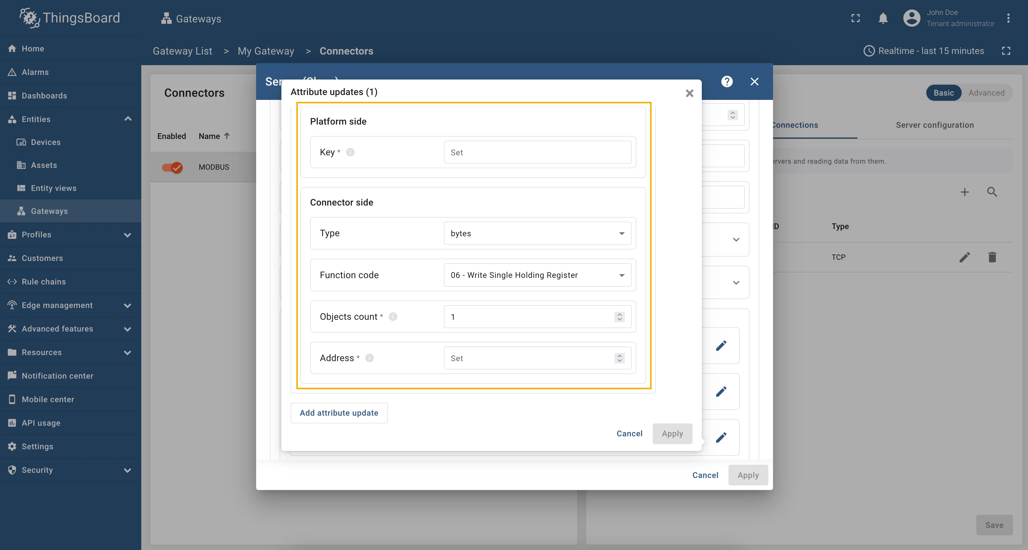
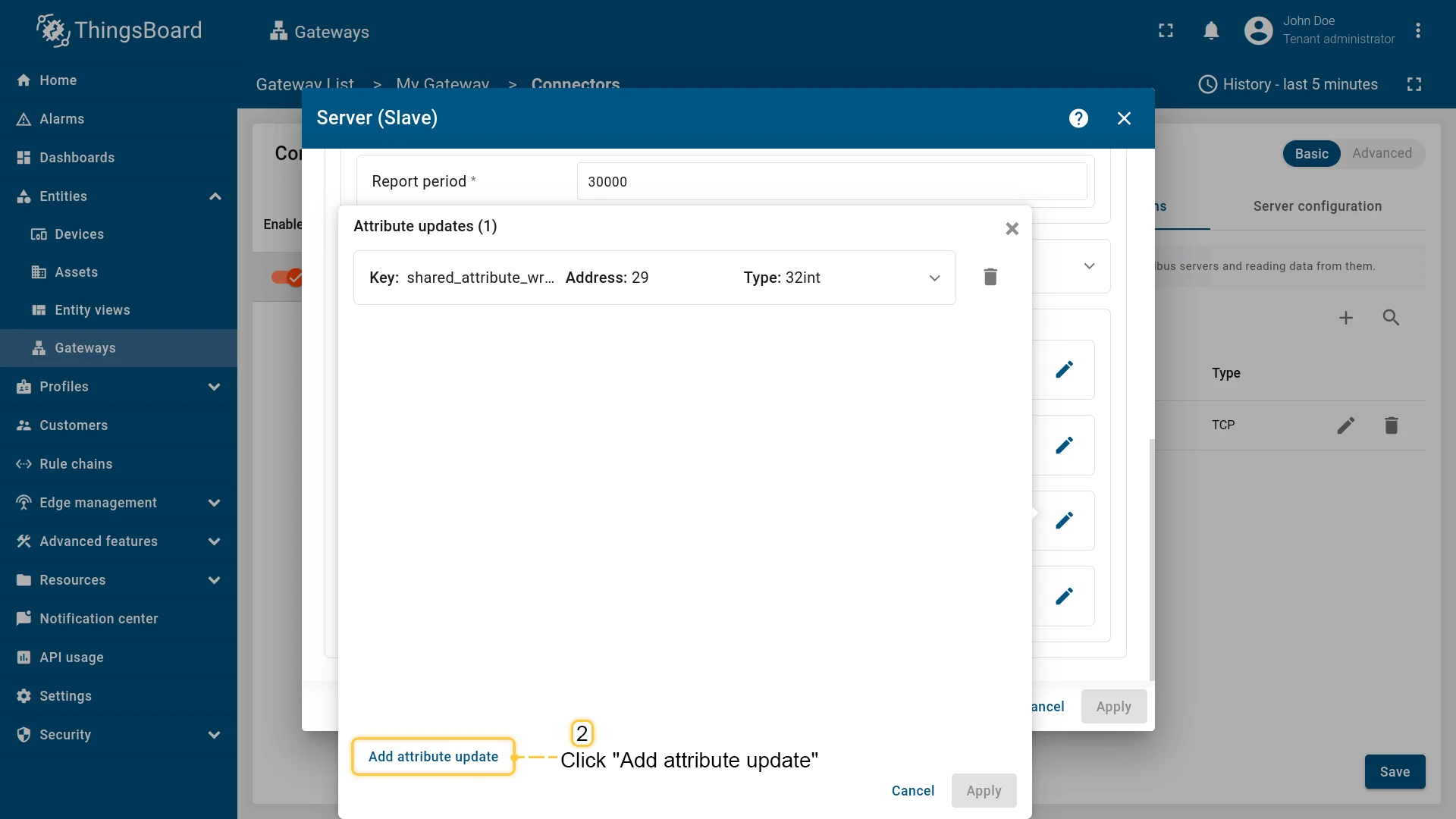
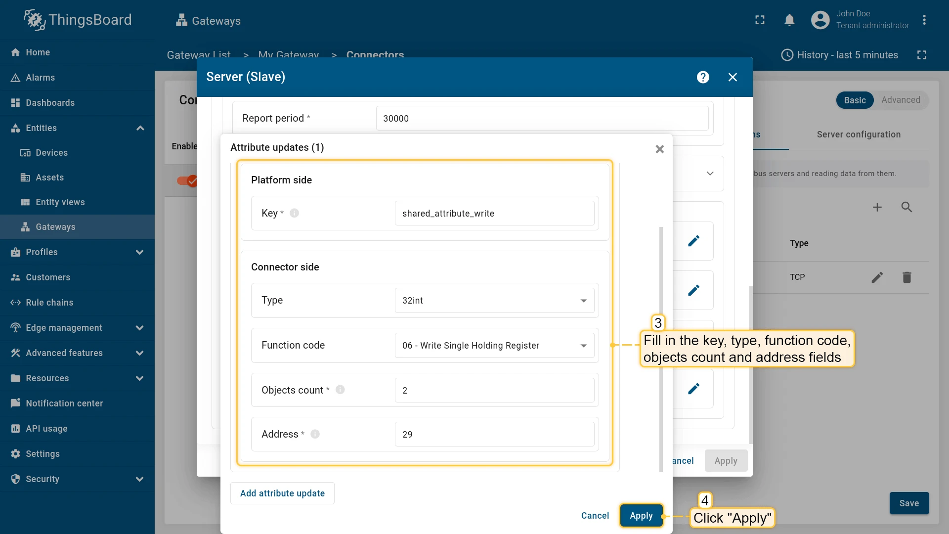
In the opened window click “Add attribute update”;

-
Set an attribute key name, type, function code, objects count, and address. Then, click “Apply”.

Subsection “RPC requests”
Section titled “Subsection “RPC requests””ThingsBoard allows sending RPC commands to the device that is connected to ThingsBoard directly or via Gateway. Configuration, provided in this section is used for sending RPC requests from ThingsBoard to device. The following parameters are used to configure RPC methods:
- Method name - RPC method name, which is used to identify the request.
- Type - data type of value, which is used to identify the data type of the value that is being received.
- Function code - function to use for data processing, specifically Modbus functions.
- Objects count - count of objects to write or read, which specifies how many registers will be processed in the request.
- Address - object address, which is used to identify the specific object in the Modbus protocol.
In order to add a new RPC method, follow these steps:
-
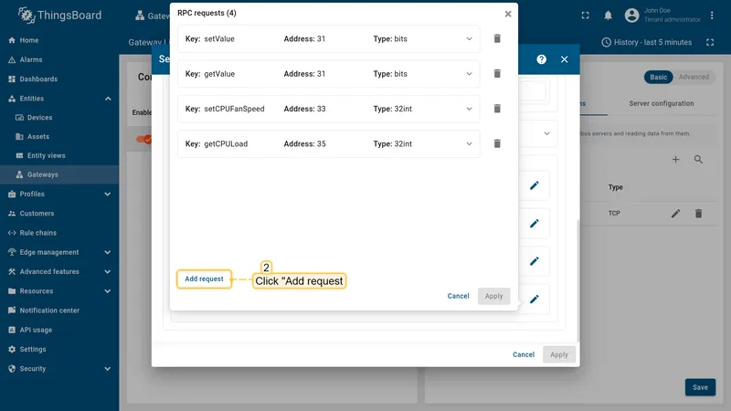
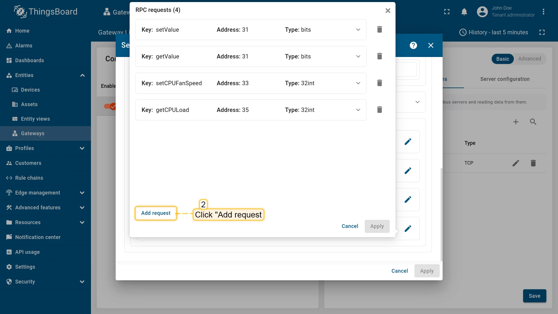
Navigate to the “RPC requests” section and click the “pencil” icon;
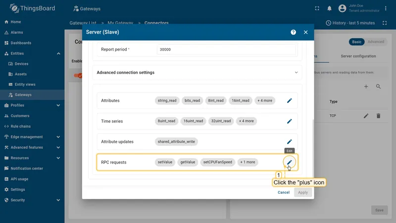
-
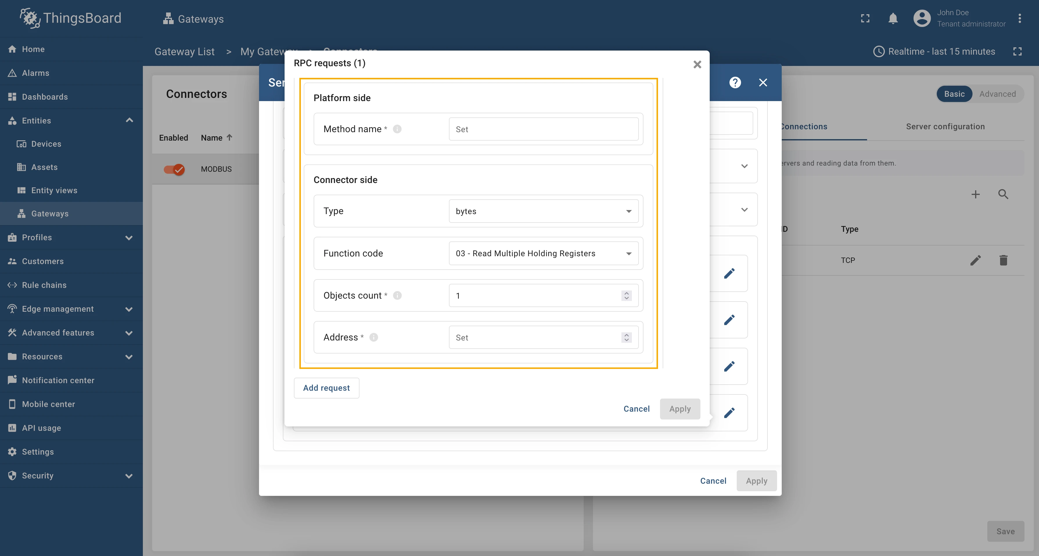
In the opened window click the “Add request”;
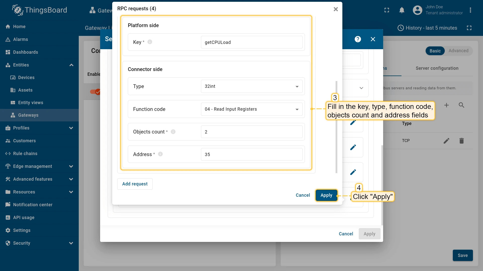
-
Fill in key, type, function code, objects count and address fields. Click “Apply”.


Usage examples
Section titled “Usage examples”Attribute updates allow you to update register values in the Modbus server. You can add new attribute updates in the “Attribute updates” section of the device configuration page.
As an example, we will use ThingsBoard Modbus Demo Server, which can be run using Docker and the following command:
docker run -it -p 5021:5021 thingsboard/tb-gw-modbus-server:latestThe server available at 0.0.0.0:5021. The server has the following structure:
| Variable Name | Register Type | Data Type | Address |
|---|---|---|---|
| Temperature | Holding | 16int | 0 |
| Humidity | Holding | 16int | 1 |
| Power | Holding | 16int | 2 |
| Pressure | Holding | 16int | 3 |
| Relay | Coil | bits | 1 |
We are interested in register “1”, we added this register as a telemetry parameter with the key relay. We used
telemetry so that later it would be convenient for us to see if the value we changed using the attribute update
has changed. You, also, can add this telemetry datapoint to the device configuration or use the reserved get method
to check the value of the node.
Let’s add an attribute update to our configuration. For this purpose, follow these steps:
-
Go to “Entities” → “Gateways” in the left sidebar and select your gateway.
-
Click on the “Connectors configuration” button on the right side menu.
-
Select the created Modbus connector and click on the “Master Connections” tab. Make sure you have configured and connected device (if you don’t know how to do it, see Getting Started guide or Connection settings and Data mapping sections of this guide). Click on the “Pencil” icon on a device you want to configure attribute updates for.
-
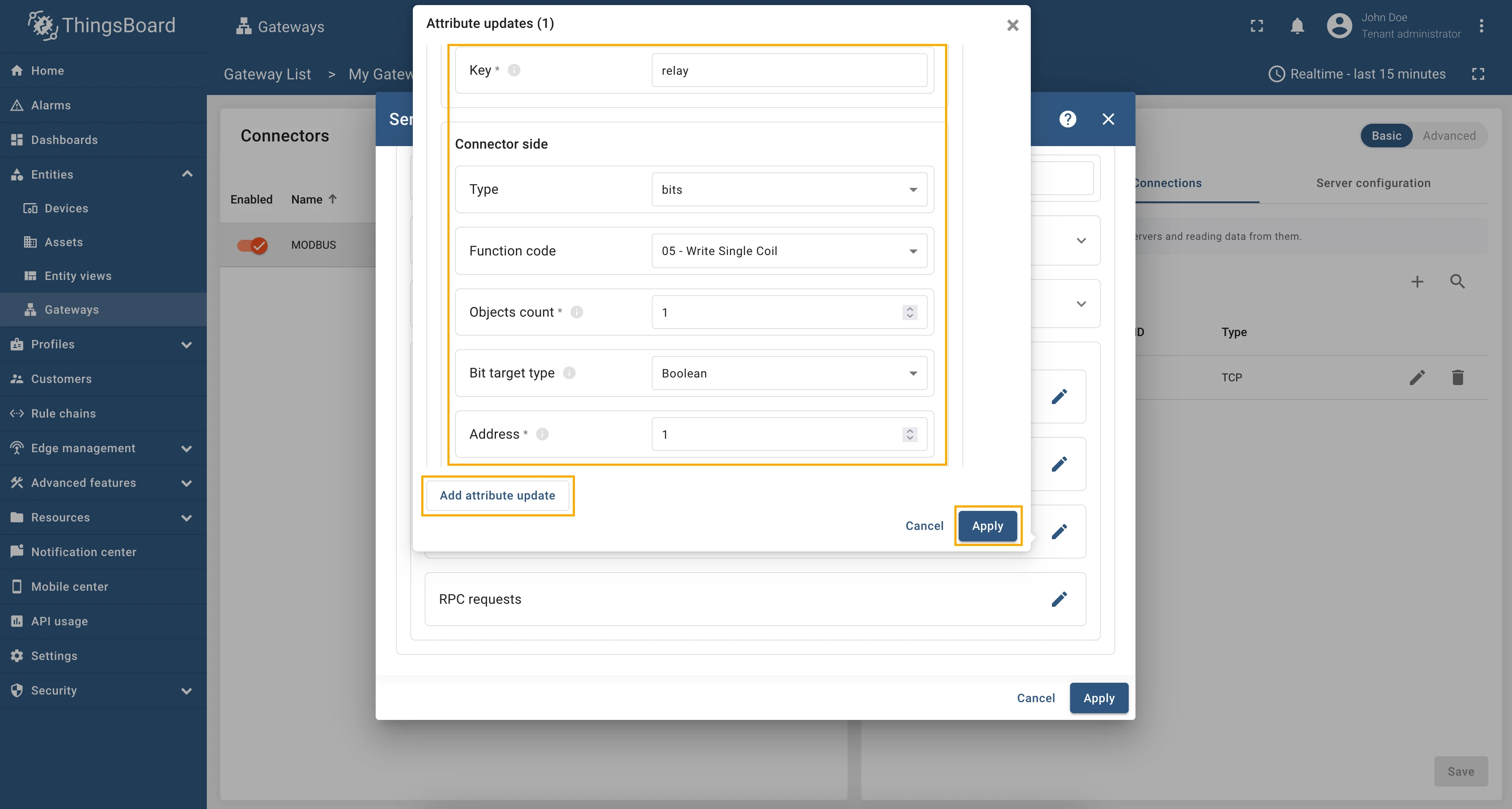
Scroll down to the “Attribute updates” section and click on the “Pencil” icon to edit the attribute updates.

-
Click on the “Add attribute update” button. In our case, we will add
relayattribute update, so the “Key” field, enterrelay, select the “Type” as bits, “Function code” as “05 - Write Single Coil”, fill in the “Objects count” field with1, select “Bit target type” as “Boolean” and in the “Address” field enter “1”.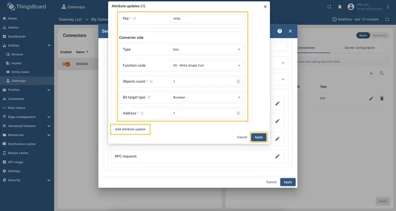
-
Remember to save your changes by clicking the “Apply” button.


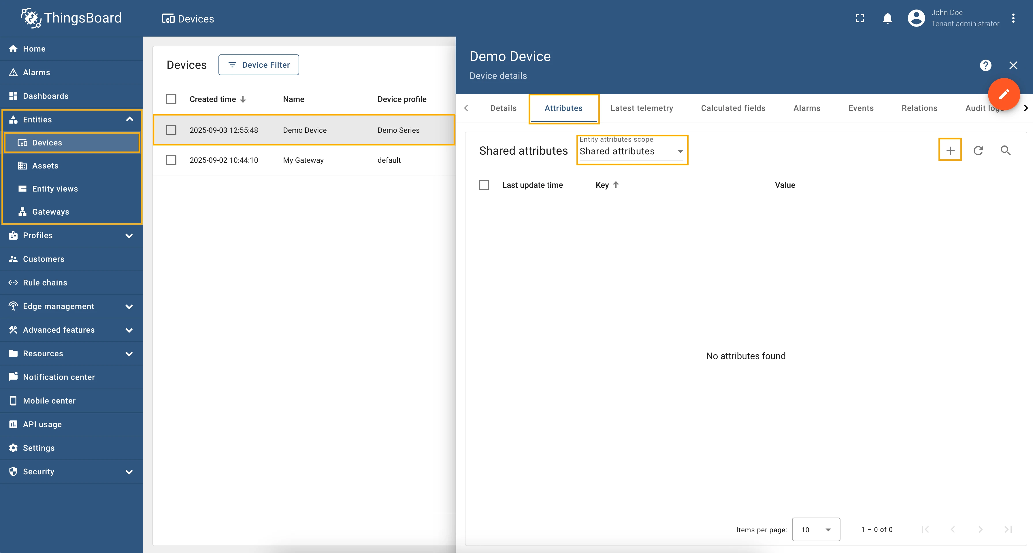
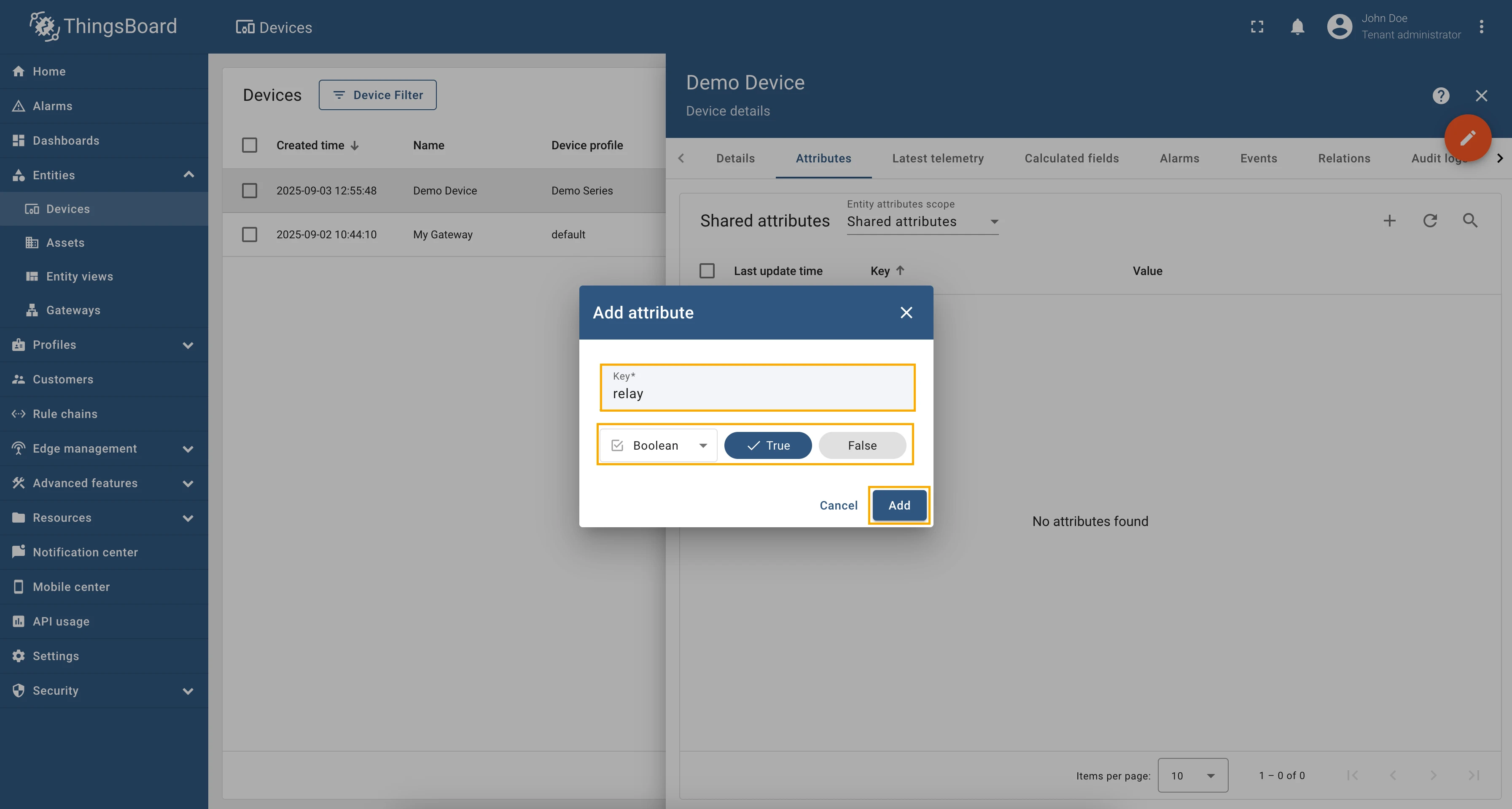
Now we can check if the attribute update works. Go to “Entities” → “Devices” → select a created
device → “Attributes” tab → select “Shared attributes” → click on the ”+” icon and add relay attribute
with type “Boolean” set it to “True”.
Now, let’s check the value of the relay register. In the selected device, go to the “Last telemetry” tab and
check the value of the relay telemetry. It should be true since we set the shared attribute to true.
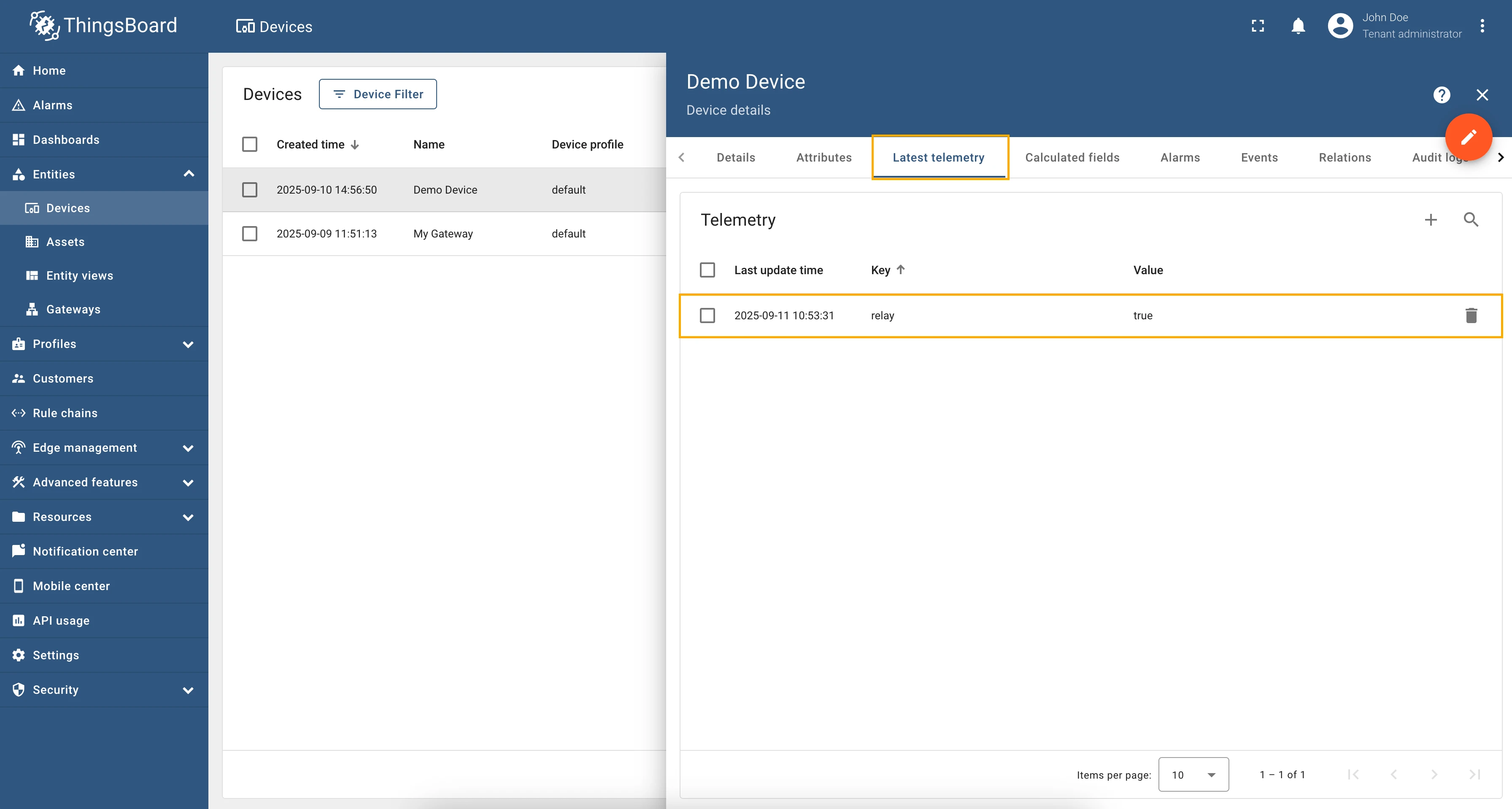
Try to change the value of the relay shared attribute to false. After a few seconds, you should see that the
relay telemetry value has changed to false, which means that the attribute update worked correctly.
Full configuration for Modbus connector for the examples above will look like this:
{ "master": { "slaves": [ { "host": "0.0.0.0", "port": 5021, "method": "socket", "unitId": 1, "deviceName": "Demo Device", "deviceType": "default", "timeout": 35, "byteOrder": "LITTLE", "wordOrder": "LITTLE", "retries": true, "retryOnEmpty": true, "retryOnInvalid": true, "pollPeriod": 1000, "connectAttemptTimeMs": 500, "connectAttemptCount": 5, "waitAfterFailedAttemptsMs": 30000, "type": "tcp", "attributes": [], "timeseries": [ { "tag": "relay", "type": "bits", "address": 1, "objectsCount": 1, "functionCode": 1, "bitTargetType": "bool" } ], "attributeUpdates": [ { "tag": "relay", "type": "bits", "address": 1, "objectsCount": 1, "functionCode": 5, "bitTargetType": "bool" } ], "rpc": [] } ] }}RPC to Device allows sending RPC commands to the device that is connected to ThingsBoard directly or via Gateway.
As an example, we will use ThingsBoard Modbus Demo Server, which can be run using Docker and the following command:
docker run -it -p 5021:5021 thingsboard/tb-gw-modbus-server:latestThe server available at 0.0.0.0:5021. The server has the following structure:
| Variable Name | Register Type | Data Type | Address |
|---|---|---|---|
| Temperature | Holding | 16int | 0 |
| Humidity | Holding | 16int | 1 |
| Power | Holding | 16int | 2 |
| Pressure | Holding | 16int | 3 |
| Relay | Coil | bits | 1 |
We are interested to get temperature value from our demo device using RPC to Device. To call this method, first, we need to configure the Modbus connector to support RPC calls. For this purpose, follow these steps:
-
Go to “Entities” → “Gateways” in the left sidebar and select your gateway.
-
Click on the “Connectors configuration” button on the right side menu.
-
Select the created Modbus connector and click on the “Master Connections” tab. Make sure you have configured and connected device (if you don’t know how to do it, see Getting Started guide or Connection settings and Data mapping sections of this guide). Click on the “Pencil” icon on a device you want to configure attribute updates for.
-
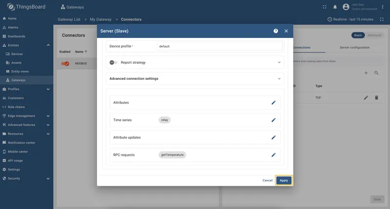
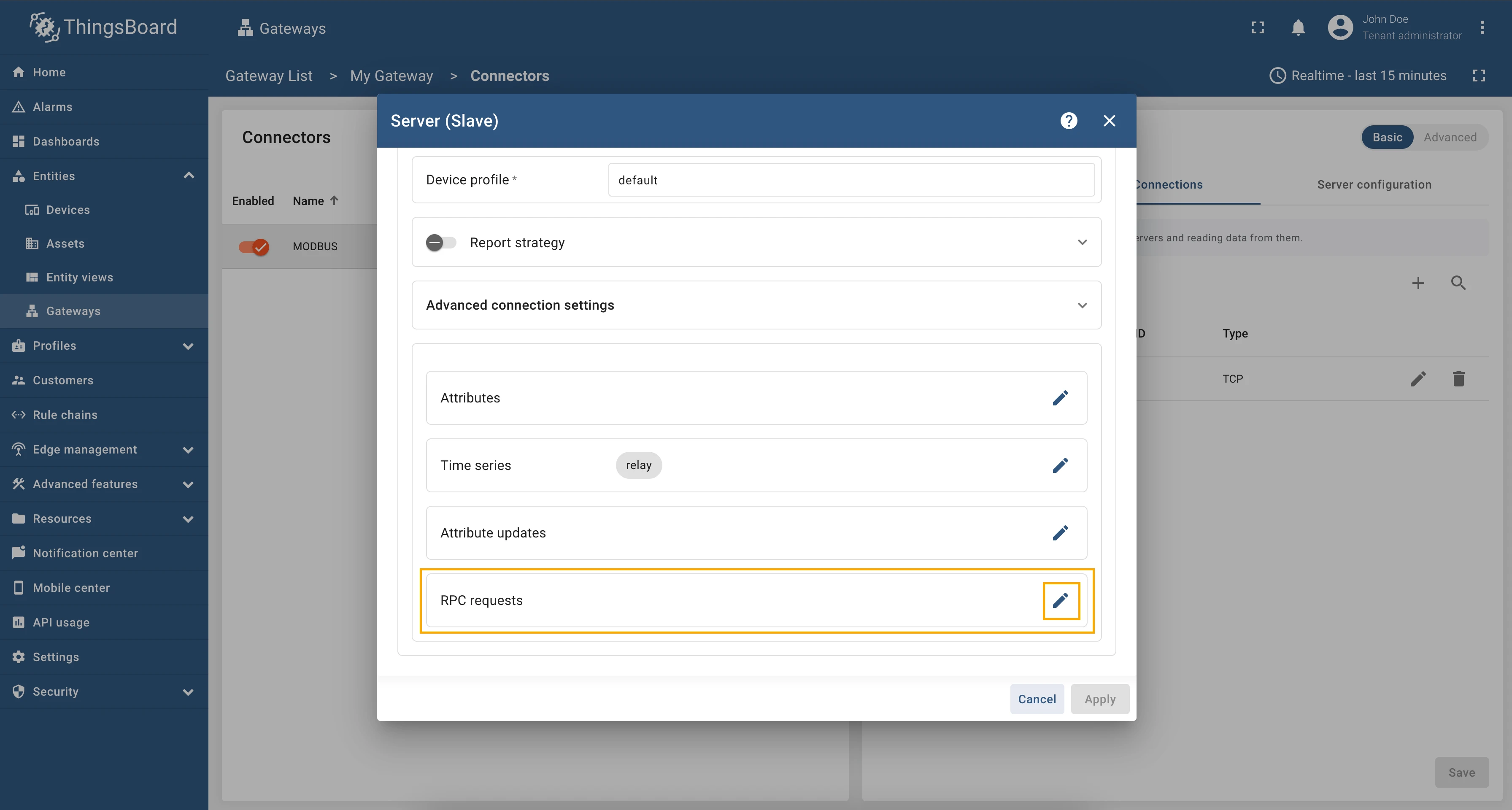
Scroll down to the “RPC requests” section and click on the “Pencil” icon to edit the RPC methods.

-
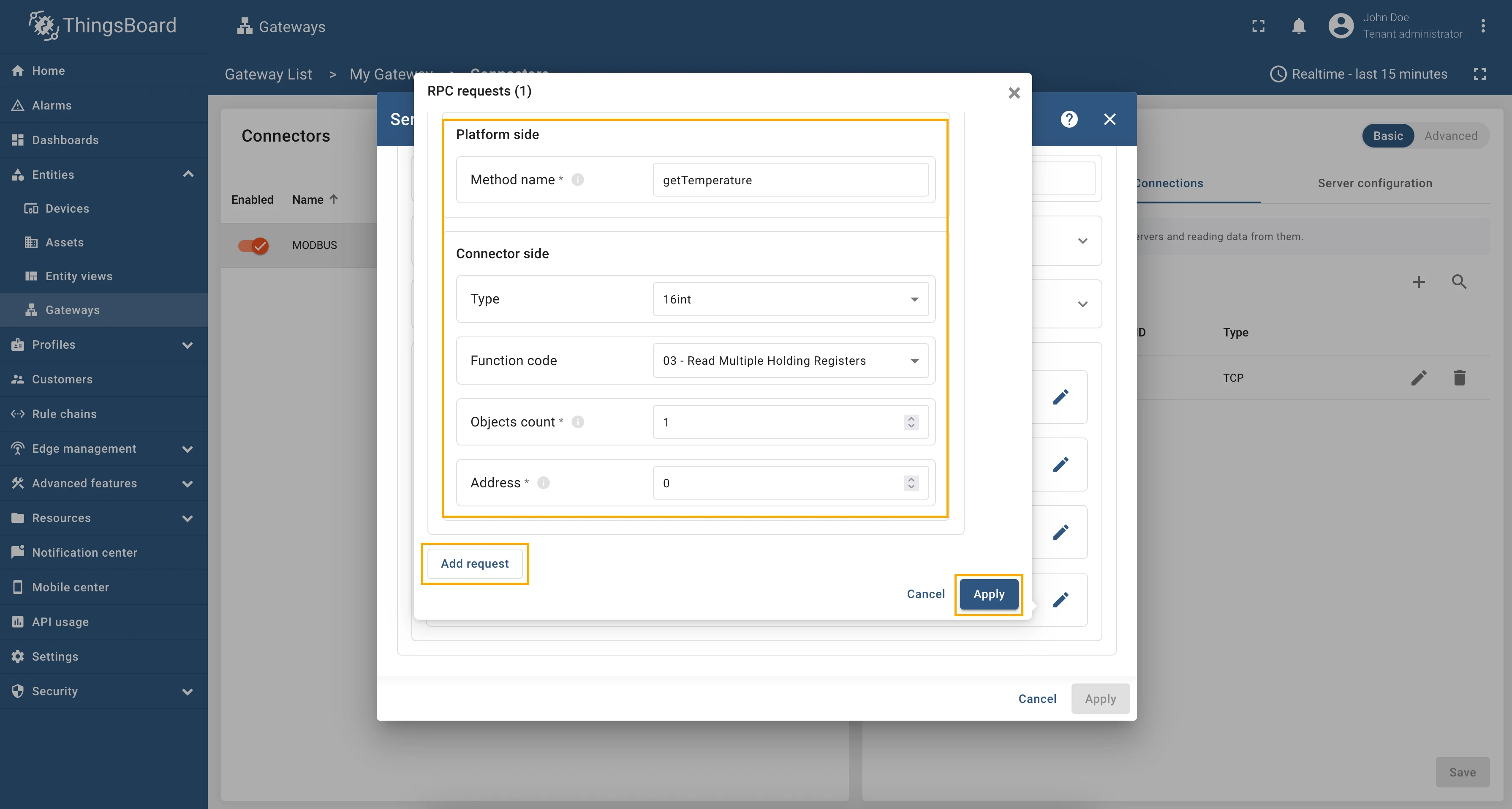
Click on the “Add request” button. Fill in the “Method” field with
getTemperature, select the “Type” as “16int”, “Function code” as “03 - Read Multiple Holding Registers”, fill in the “Objects count” field with1, and in the “Address” field enter “0”.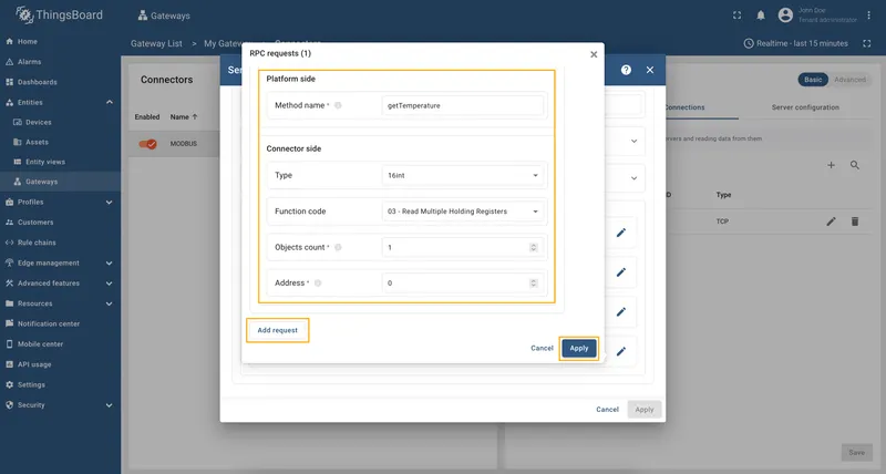
-
Remember to save your changes by clicking the “Apply” button.

We are done with configuration, so let’s check how to call the method. In the RPC Debug Terminal widget, run the following command:
getTemperatureResponse:
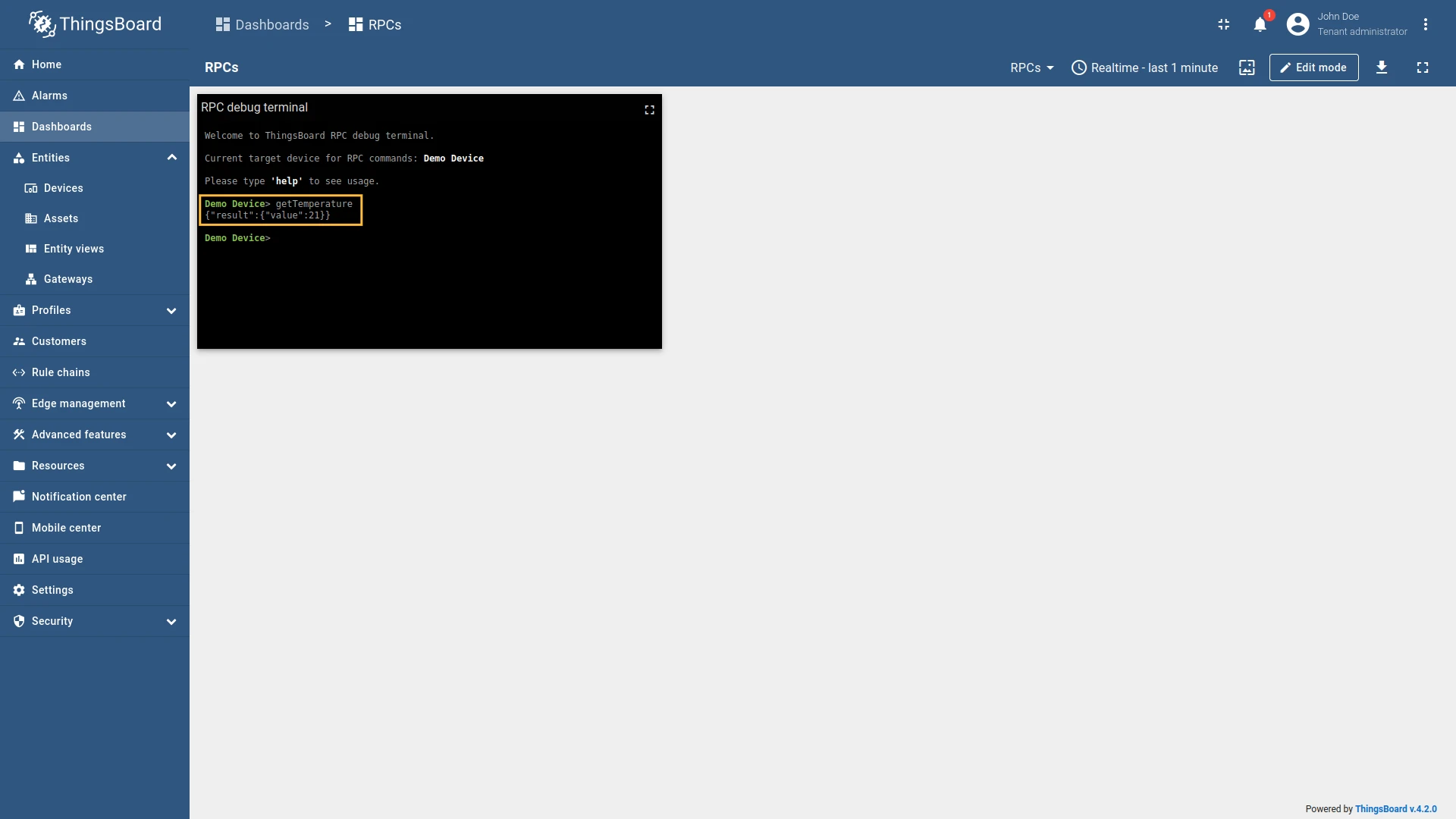
Full configuration for Modbus connector for the example above will look like this:
{ "master": { "slaves": [ { "host": "0.0.0.0", "port": 5021, "method": "socket", "unitId": 1, "deviceName": "Demo Device", "deviceType": "default", "timeout": 35, "byteOrder": "LITTLE", "wordOrder": "LITTLE", "retries": true, "retryOnEmpty": true, "retryOnInvalid": true, "pollPeriod": 1000, "connectAttemptTimeMs": 500, "connectAttemptCount": 5, "waitAfterFailedAttemptsMs": 30000, "type": "tcp", "attributes": [], "timeseries": [ { "tag": "some_key", "type": "16int", "address": 0, "objectsCount": 1, "functionCode": 3 } ], "attributeUpdates": [], "rpc": [ { "tag": "getTemperature", "type": "16int", "address": 0, "objectsCount": 1, "functionCode": 3 } ] } ] }}Every telemetry and attribute parameter has GET and SET RPC methods out of the box, so you don’t need to configure
them manually.
As an example, we will use ThingsBoard Modbus Demo Server, which can be run using Docker and the following command:
docker run -it -p 5021:5021 thingsboard/tb-gw-modbus-server:latestThe server available at 0.0.0.0:5021. The server has the following structure:
| Variable Name | Register Type | Data Type | Address |
|---|---|---|---|
| Temperature | Holding | 16int | 0 |
| Humidity | Holding | 16int | 1 |
| Power | Holding | 16int | 2 |
| Pressure | Holding | 16int | 3 |
| Relay | Coil | bits | 1 |
We are interested in register 1, which is a coil register. We will use this register to set the value of the
telemetry parameter. The register is of type bits, so we will use bits type for the telemetry parameter. The
configuration for this telemetry will look like this:
{ "tag": "relay", "type": "bits", "address": 1, "objectsCount": 1, "functionCode": 1, "bitTargetType": "bool"}Let’s check the value of the relay register using the reserved get method. To get the current value of relay
register, run the query in RPC debug terminal:
get type=bits;functionCode=1;objectsCount=1;address=1;Response:
{"result":{"value":false}}
So, the get method returns the current value of the relay register, and we can see that the relay is off.
To set the value of the relay register and turn it on, run the query:
set type=bits;functionCode=5;objectsCount=1;address=1;value=1;Response:
{"result":{"value":"1"}}And as you can see, from the screenshot below, the relay telemetry value has changed to 1:

Also, let’s check the value of the relay telemetry again: it is true
now because, in the Modbus connector, booleans come from integers — 0 = false, 1 = true
(any non-zero is true) — so a register value of 1 is reported as true.
get type=bits;functionCode=3;objectsCount=1;address=1;Response:
{"result":{"value":true}}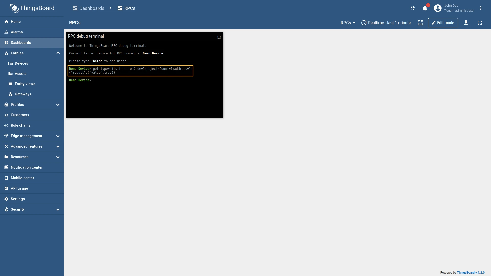
Full configuration for Modbus connector for the examples above will look like this:
{ "master": { "slaves": [ { "host": "0.0.0.0", "port": 5021, "method": "socket", "unitId": 1, "deviceName": "Demo Device", "deviceType": "default", "timeout": 35, "byteOrder": "LITTLE", "wordOrder": "LITTLE", "retries": true, "retryOnEmpty": true, "retryOnInvalid": true, "pollPeriod": 1000, "connectAttemptTimeMs": 500, "connectAttemptCount": 5, "waitAfterFailedAttemptsMs": 30000, "type": "tcp", "attributes": [], "timeseries": [ { "tag": "relay", "type": "bits", "address": 1, "objectsCount": 1, "functionCode": 1, "bitTargetType": "bool" } ], "attributeUpdates": [], "rpc": [] } ] }}Advanced configuration
Section titled “Advanced configuration”The advanced configuration section provides a detailed overview of all available parameters for the Master section configuration.
Master
Section titled “Master”Gateway can run as a Modbus master. This configuration section for the Modbus master, which is used to query data from Modbus servers (slaves).
Slaves
Section titled “Slaves”The Slaves list is used to specify the list of Modbus slaves that the master will query data from.
| Parameter | Default value | Description |
|---|---|---|
| server.slaves[].unitId | Unit ID of Modbus slave. | |
| server.slaves[].deviceName | Device name on the platform. | |
| server.slaves[].deviceType | default | (Optional) Device profile name on the platform. |
| server.slaves[].pollPeriod (in ms) | Period in milliseconds to check the attributes and the telemetry on the slave. | |
| server.slaves[].delayBetweenRequestsMs | 0 | (Optional) Delay between reading and writing requests. Useful for devices that implement Modbus RTU over TCP internally consist of a TCP-to-Serial converter. |
| server.slaves[].timeout (in sec) | 35 | (Optional) Timeout in seconds for connecting to Modbus server. |
| server.slaves[].retries | true | (Optional) Retrying sending data to the master. The values can be either: true or false. |
| server.slaves[].retryOnEmpty | true | (Optional) Retrying sending data to the master if it is empty. |
| server.slaves[].retryOnInvalid | true | (Optional) Retrying sending data to the master if it is failed. |
| server.slaves[].connectAttemptTimeMs (in ms) | 5000 | (Optional) A waiting period in milliseconds before connecting to the master. |
| server.slaves[].connectAttemptCount | 5 | (Optional) The number of connection attempts made through the ThingsBoard gateway. |
| server.slaves[].waitAfterFailedAttemptsMs (in ms) | 300000 | (Optional) A waiting period in milliseconds before trying to send data to the master. |
| server.slaves[].byteOrder | LITTLE | Order of bytes to read. |
| server.slaves[].wordOrder | LITTLE | The order of words when reading several registers. |
| server.slaves[].reportStrategy | (Optional) Report strategy object using for configuring report strategy for device. |
Example of the slave configuration:
"master": { "slaves": [ { "timeout": 35, "byteOrder": "LITTLE", "wordOrder": "LITTLE", "retries": true, "retryOnEmpty": true, "retryOnInvalid": true, "pollPeriod": 5000, "sendDataOnlyOnChange": true, "connectAttemptTimeMs": 5000, "connectAttemptCount": 5, "waitAfterFailedAttemptsMs": 300000, "deviceName": "Demo Device", "deviceType": "default", "unitId": 1, ... } ]}Slave connection types
Section titled “Slave connection types”The Modbus connector supports three types of connections to the Modbus slave:
- TCP - connection to the Modbus slave over TCP/IP protocol.
- UDP - connection to the Modbus slave over UDP protocol.
- Serial - connection to the Modbus slave over serial port (RS-232, RS-485, etc.).
TCP/UDP
Section titled “TCP/UDP”| Parameter | Default value | Description |
|---|---|---|
| master.slaves[].type | Type of connection to Modbus device. | |
| master.slaves[].host | localhost | Hostname or ip address of Modbus server. |
| master.slaves[].port | 5021 | Port of Modbus server for connection. |
| master.slaves[].method | socket | Type of a framer Socket or RTU, if needed. |
Example of the TCP/UDP slave configuration:
"master": { "slaves": [ { "host": "127.0.0.1", "port": 5021, "method": "socket", ... } ]}Serial
Section titled “Serial”| Parameter | Default value | Description |
|---|---|---|
| master.slaves[].type | serial | Type of connection to Modbus device. |
| master.slaves[].port | Port of Modbus slave for connection. | |
| master.slaves[].method | socket | Type of a framer Socket or RTU, if needed. |
| master.slaves[].baudrate | 19200 | Baud rate for serial connection. |
| master.slaves[].stopbits | 1 | (Optional) The number of bits sent after each character in a message to indicate the end of the byte. |
| master.slaves[].parity | None | (Optional) The type of checksum to use to verify data integrity. This can be on of the following: (E)ven, (O)dd, (N)one. |
| master.slaves[].bytesize | 8 | (Optional) The number of bits in a byte of serial data. This can be one of 5, 6, 7, or 8. |
| master.slaves[].strict | true | (Optional) Use Inter char timeout for baud rates less than or equal to 19200 |
| master.slaves[].repack | false | (Optional) Repack data to remove padding bytes. |
| master.slaves[].handleLocalEcho | false | (Optional) Handle local echo for serial connections. This is useful for devices that echo back the data sent to them. |
Example of the serial slave configuration:
"master": { "slaves": [ { "method": "ascii", "baudrate": 4800, "stopbits": 1, "bytesize": 5, "parity": "N", "strict": true, ... } ]}Device attributes and time series
Section titled “Device attributes and time series”| Parameter | Description |
|---|---|
| server.slaves[].attributes[] | List of attributes that will be sent to the ThingsBoard platform instance. |
| server.slaves[].attributes[].tag | Key name of the attribute in ThingsBoard. It can be specified as a static value. |
| server.slaves[].attributes[].type | Data type of value. |
| server.slaves[].attributes[].functionCode | Function code to use for reading the attribute value from the Modbus slave. |
| server.slaves[].attributes[].objectsCount | Number of objects to read from the Modbus slave. |
| server.slaves[].attributes[].address | Address of the object in the Modbus slave. Can be configured for batch reading. |
| server.slaves[].attributes[].divider | (Optional) Divider for the value. If not specified, the value will be sent as is. |
| server.slaves[].attributes[].multiplier | (Optional) Multiplier for the value. If not specified, the value will be sent as is. |
| server.slaves[].attributes[].bitTargetType | The response type can be either an integer (0/1) or a boolean (True/False). Used only with type bits. |
| mapping[].attributes[].reportStrategy | (Optional) Report strategy for the attributes data. If not specified, the device report strategy will be used. |
| server.slaves[].timeseries[] | List of time series that will be sent to the ThingsBoard platform instance. |
| server.slaves[].timeseries[].tag | Key name of the time series in ThingsBoard. It can be specified as a static value. |
| server.slaves[].timeseries[].type | Data type of value. |
| server.slaves[].timeseries[].functionCode | Function code to use for reading the time series value from the Modbus slave. |
| server.slaves[].timeseries[].objectsCount | Number of objects to read from the Modbus slave. |
| server.slaves[].timeseries[].address | Address of the object in the Modbus slave. Can be configured for batch reading. |
| server.slaves[].timeseries[].divider | (Optional) Divider for the value. If not specified, the value will be sent as is. |
| server.slaves[].timeseries[].multiplier | (Optional) Multiplier for the value. If not specified, the value will be sent as is. |
| server.slaves[].timeseries[].bitTargetType | The response type can be either an integer (0/1) or a boolean (True/False). Used only with type bits. |
| mapping[].attributes[].reportStrategy | (Optional) Report strategy for the time series data. If not specified, the device report strategy will be used. |
Example of the attributes and telemetry configuration:
"attributes": [ { "tag": "string_read", "type": "string", "functionCode": 4, "objectsCount": 4, "address": 1 }],"timeseries": [ { "tag": "16uint_read", "type": "16uint", "functionCode": 4, "objectsCount": 2, "address": 18 },]Device attributes updates
Section titled “Device attributes updates”| Parameter | Description |
|---|---|
| server.slaves[].attributeUpdates[] | List of attributes that will be updated on the device. |
| server.slaves[].attributeUpdates[].tag | Key name of the shared attribute in ThingsBoard. It can be specified as a static value. |
| server.slaves[].attributeUpdates[].type | Data type of value. |
| server.slaves[].attributeUpdates[].functionCode | Function code to use for reading the attribute value from the Modbus slave. |
| server.slaves[].attributeUpdates[].objectsCount | Number of objects to read from the Modbus slave. |
| server.slaves[].attributeUpdates[].address | Address of the object in the Modbus slave. |
| server.slaves[].attributeUpdates[].timeout (in ms) | (Optional) Timeout for the request in milliseconds. If not specified, the default timeout is used (5 sec). |
| server.slaves[].attributeUpdates[].bitTargetType | The response type can be either an integer (0/1) or a boolean (True/False). Used only with type bits. |
Example of the attributes updates configuration:
{ "tag": "relay", "type": "bits", "functionCode": 5, "objectsCount": 1, "bitTargetType": "int", "address": 29}Device RPC methods
Section titled “Device RPC methods”| Parameter | Description |
|---|---|
| server.slaves[].rpc[] | List of RPC methods that will be available on the device. |
| server.slaves[].rpc[].tag | Name of the RPC method. It can be specified as a static value. |
| server.slaves[].rpc[].type | Data type of value. |
| server.slaves[].rpc[].functionCode | Function code to use for reading the RPC method value from the Modbus slave. |
| server.slaves[].rpc[].objectsCount | Number of objects to read from the Modbus slave. |
| server.slaves[].rpc[].address | Address of the object in the Modbus slave. |
| server.slaves[].rpc[].timeout (in ms) | (Optional) Timeout for the request in milliseconds. If not specified, the default timeout is used (5 sec). |
| server.slaves[].rpc[].bitTargetType | The response type can be either an integer (0/1) or a boolean (True/False). Used only with type bits. |
Example of the RPC methods configuration:
"rpc": [ { "tag": "setValue", "type": "16int", "functionCode": 6, "objectsCount": 1, "address": 31 }]Server (Gateway as a Slave) settings
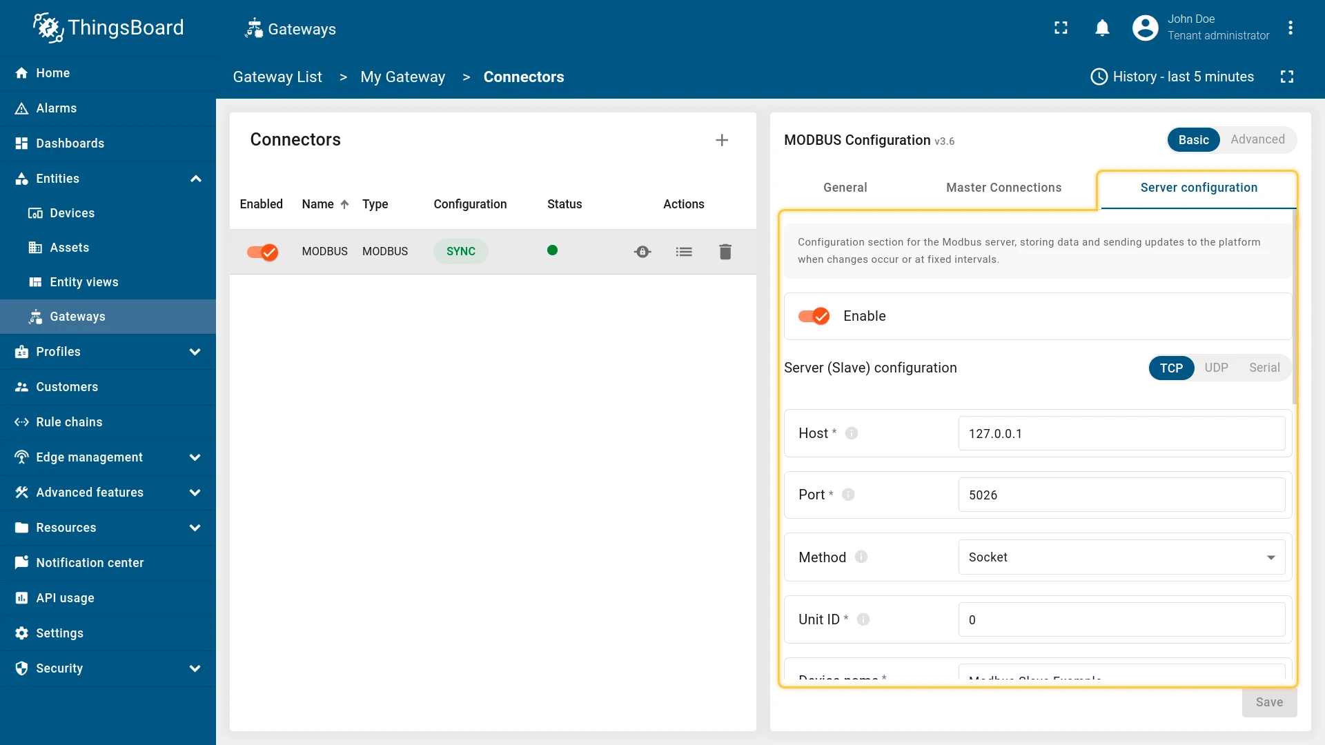
Section titled “Server (Gateway as a Slave) settings”Gateway can run as a Modbus slave. Gateway as a slave can store data, send updates to the platform when changes occur or at fixed intervals, also, user can change storing data via RPCs or shared attribute updates.
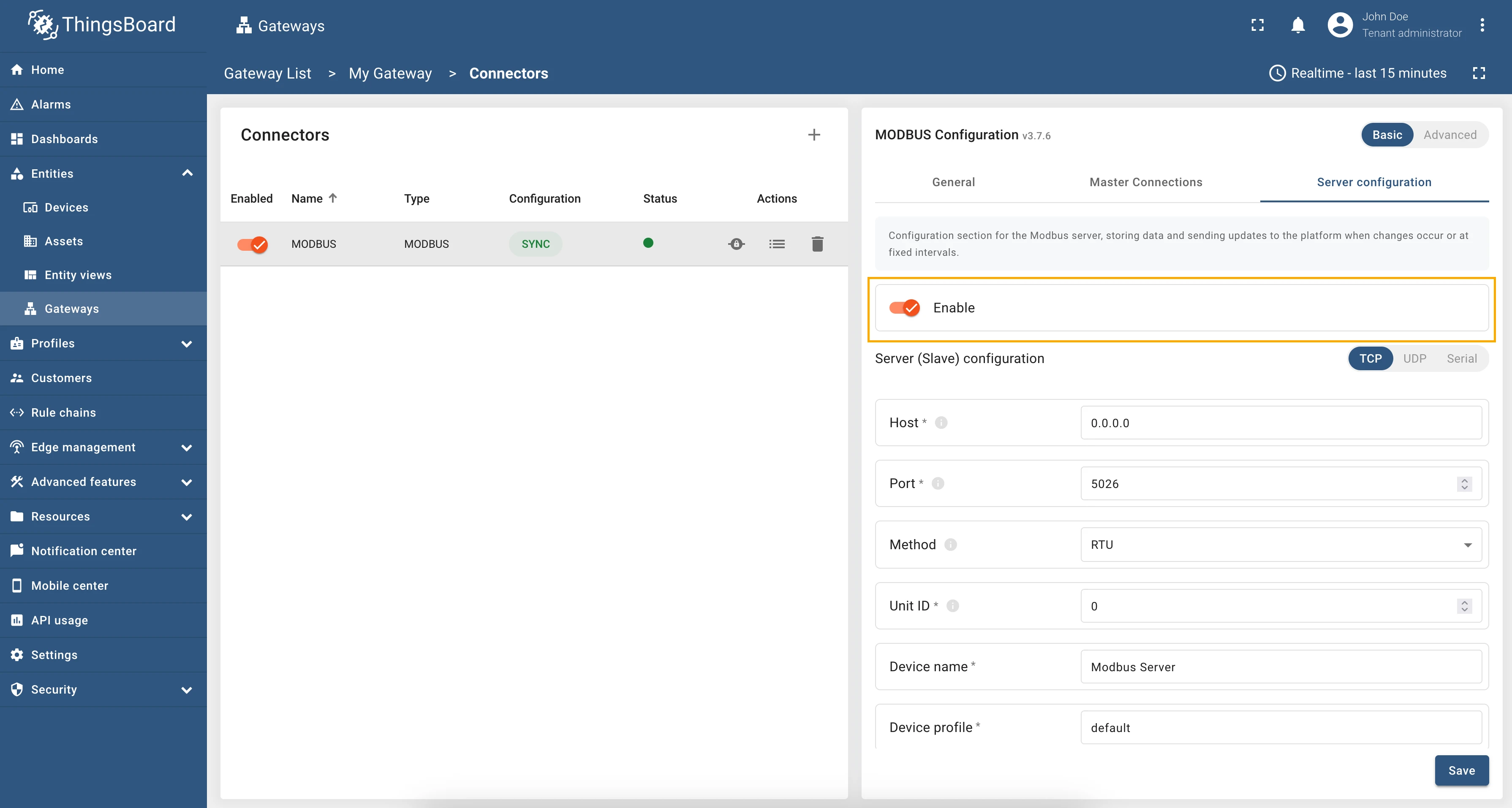
Enabling Gateway as a Slave and sending data to the platform
Section titled “Enabling Gateway as a Slave and sending data to the platform”To enable the Gateway as a Modbus slave, you need to toggle “Enable” button in the “Server configuration” section. Please note that this option will only create a modbus slave, but it will not send any data to the platform automatically:
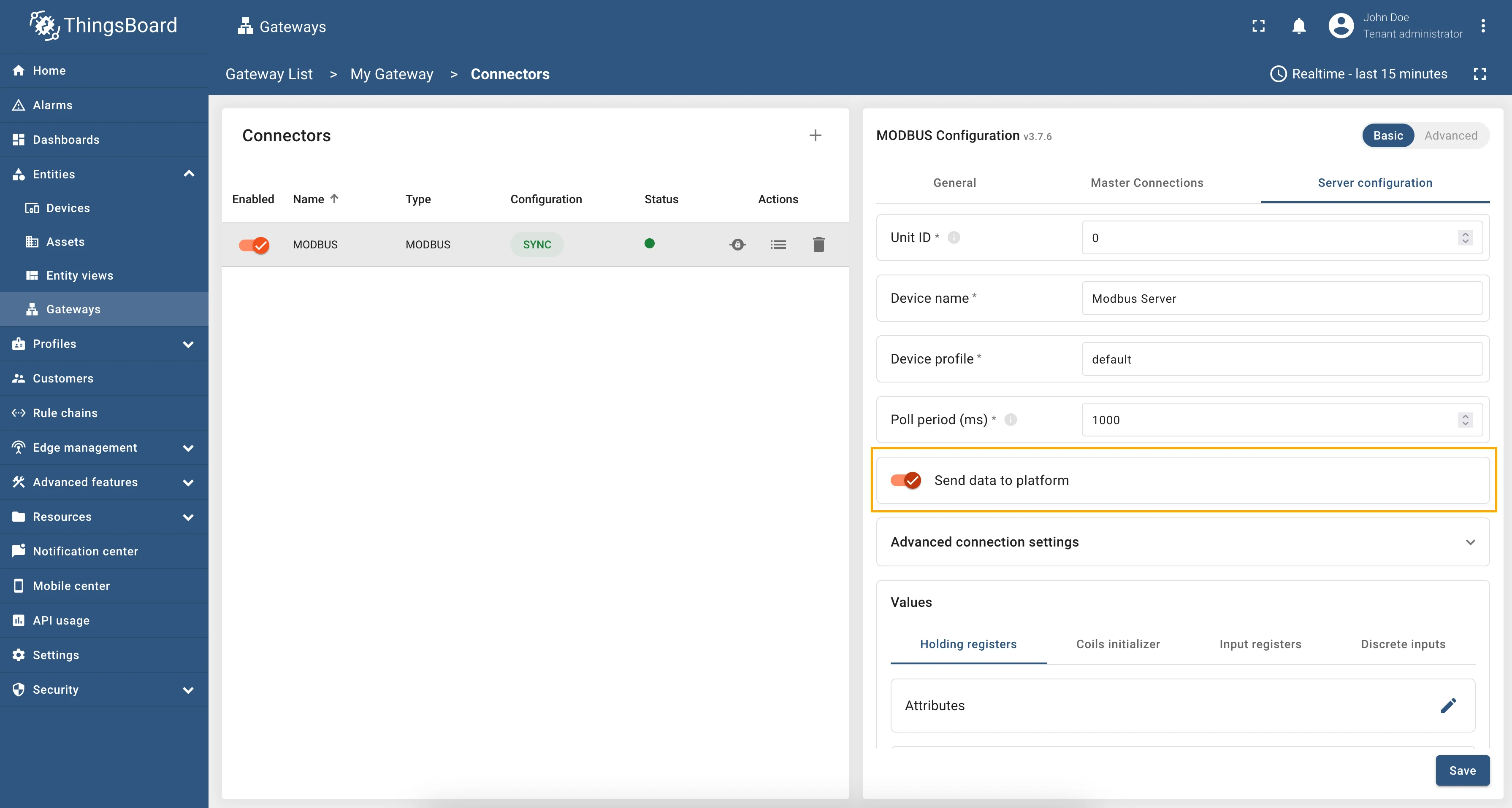
To send data to the platform, you need to enable “Send data to the platform” toggle in the “Server configuration”, which will enable sending data to the platform when changes occur or at fixed intervals:
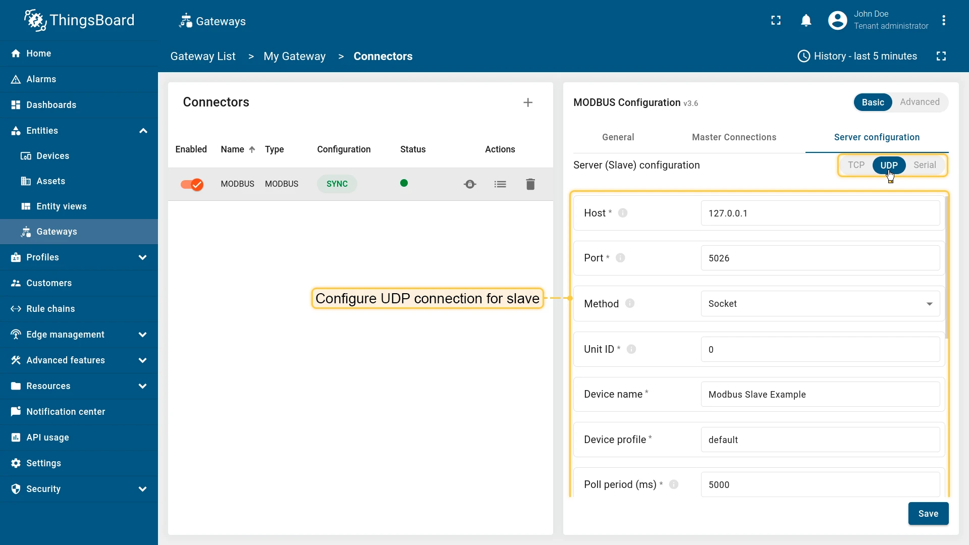
Connection settings
Section titled “Connection settings”Due to the nature of preferred way of communication between Modbus master there are 3 options how to configure this part: TCP, UDP or via Serial port.
The following parameters are used to configure TCP connection for Gateway as a Slave:
- Host - hostname or IP address of the Modbus server.
- Port - port of the Modbus server for connection.
- Method - type of a framer, either Socket or RTU.
- Unit ID - ID of the current slave on Modbus.
- Device name - name of the current slave. Don’t use “Gateway” as the value of “Device name” parameter!
- Device profile - device profile of the current slave.
- Poll period (ms) - period in milliseconds for checking the attributes and telemetry.

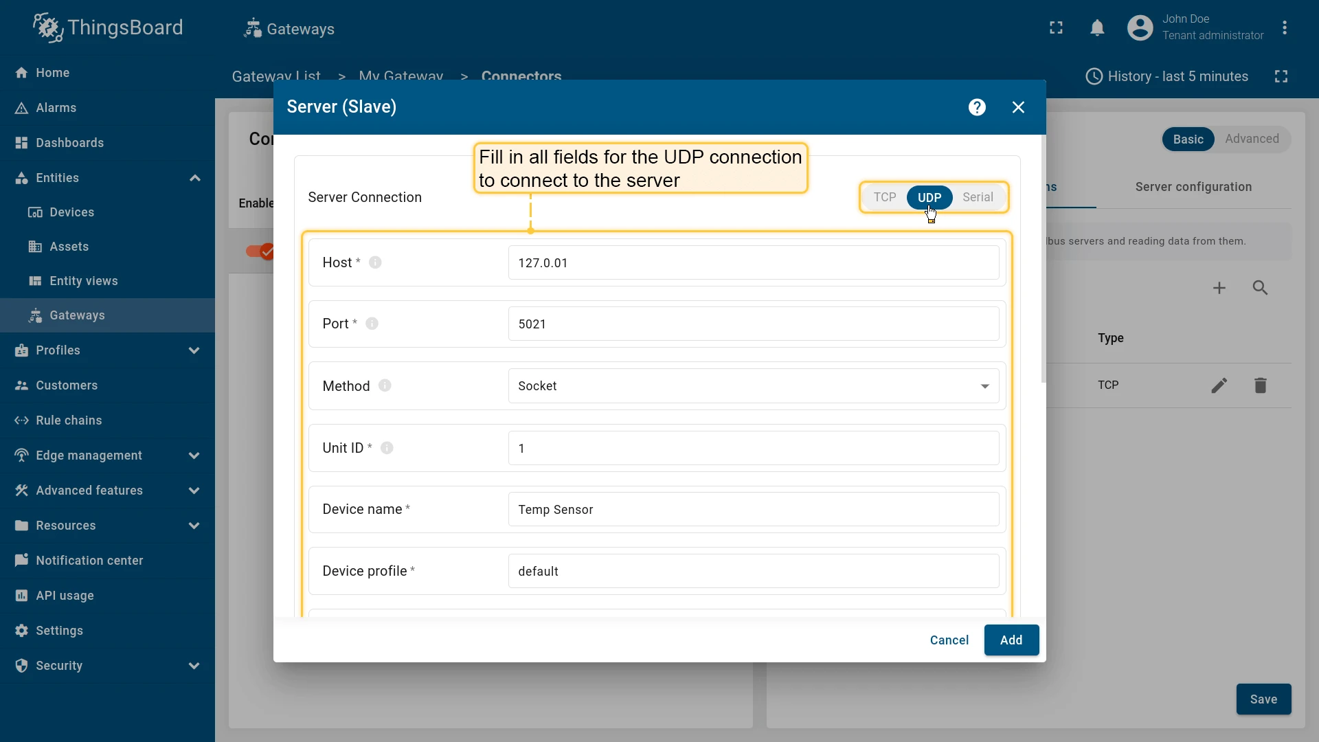
The following parameters are used to configure UDP connection for Gateway as a Slave:
- Host - hostname or IP address of the Modbus server.
- Port - port of the Modbus server for connection.
- Method - type of a framer, either Socket or RTU.
- Unit ID - ID of the current slave on Modbus.
- Device name - name of the current slave. Don’t use “Gateway” as the value of “Device name” parameter!
- Device profile - device profile of the current slave.
- Poll period (ms) - period in milliseconds for checking the attributes and telemetry.
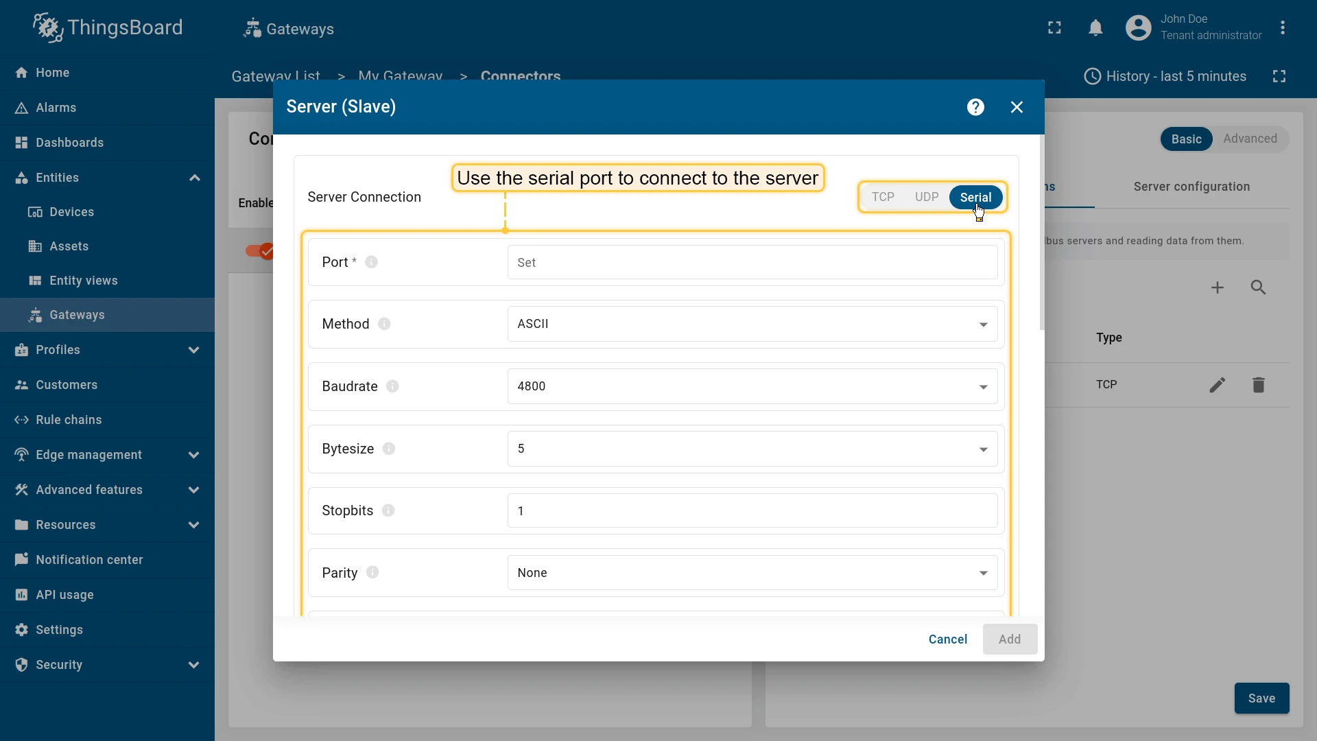
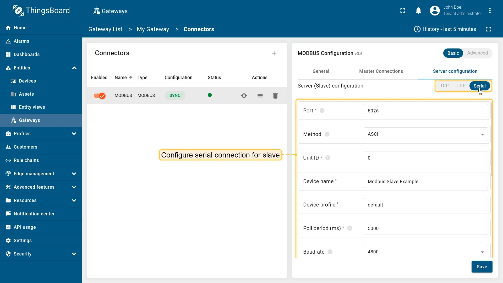
The following parameters are used to configure serial connection for Gateway as a Slave:
- Port - port of the Modbus server for connection.
- Method - type of application data unit, either ASCII or RTU.
- Baudrate - baud rate to use for the serial device.
- Strict - use inter-character timeout for baud rates less than or equal to 19200.
- Unit ID - ID of the current slave on Modbus.
- Device name - name of the current slave. Don’t use “Gateway” as the value of “Device name” parameter!.
- Device profile - device profile of the current slave.
- Poll period (ms) - period in milliseconds for checking the attributes and telemetry.
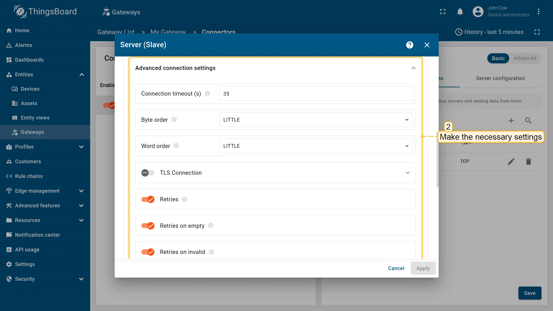
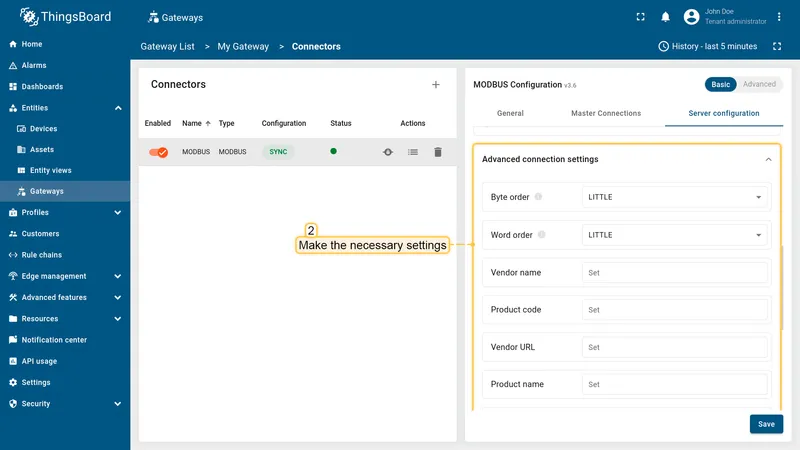
Advanced connection settings
Section titled “Advanced connection settings”You can configure additional settings like: TLS connection, byte order, word order, and other. The following parameters are used to configure advanced connection settings:
- Byte order - byte order for the Modbus connection, either LITTLE or BIG.
- Word order - word order for the Modbus connection, either LITTLE or BIG.
- Vendor name - name of the vendor for the Modbus connection.
- Product code - product code for the Modbus connection.
- Vendor URL - URL of the vendor for the Modbus connection.
- Product name - name of the product for the Modbus connection.
- Model name - model name for the Modbus connection.
- TLS - enable or disable TLS connection for the Modbus connection (Only for TCP and UDP connections):
- Path to client certificate - path to the client certificate file.
- Path to client private key - path to the client private key file.
- Password - password for the client private key file.
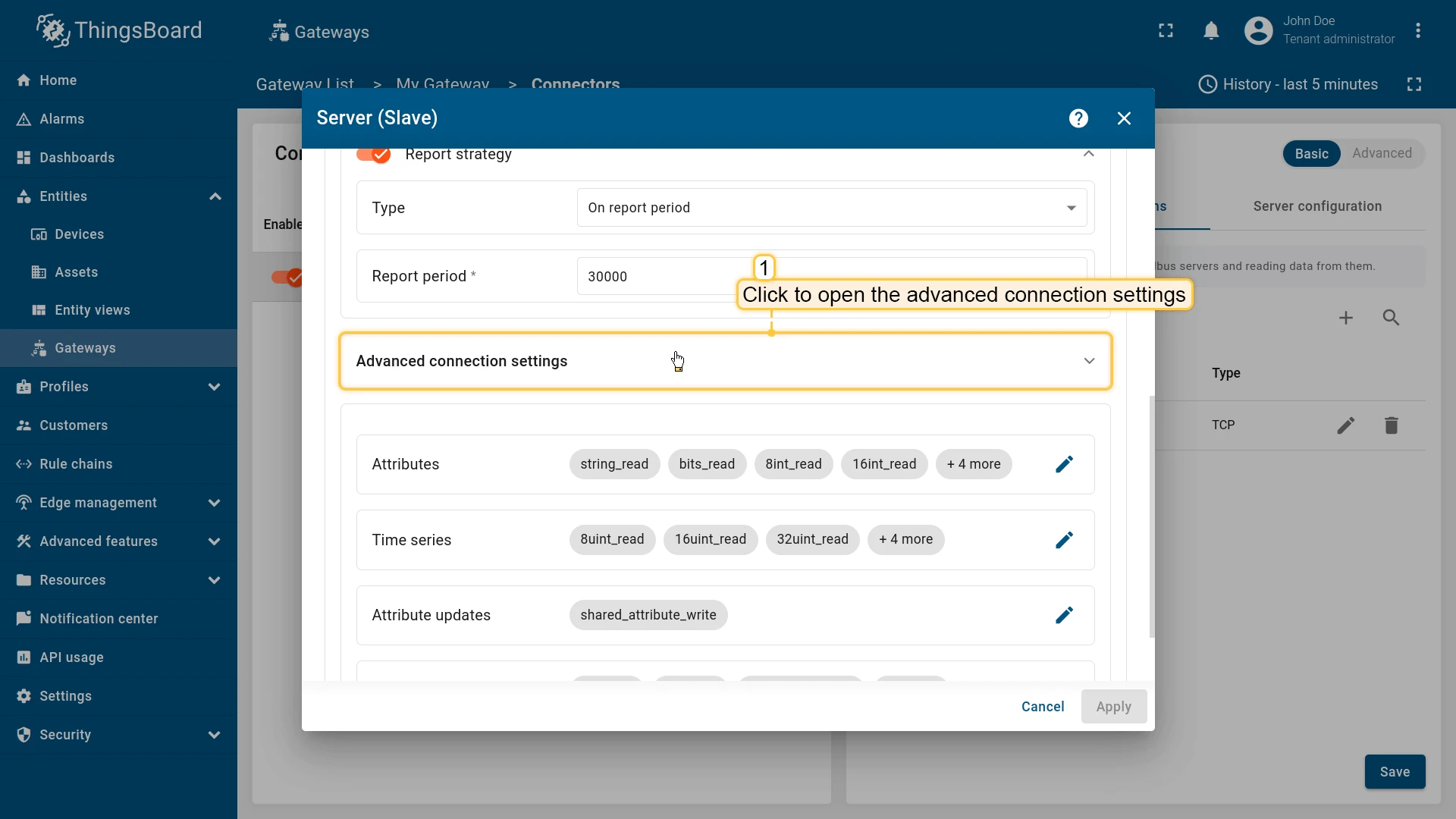
To configure advanced connection settings, follow these steps:
-
Click on the “Advanced connection settings” subsection to open it;
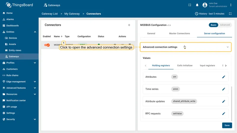
-
Make the necessary settings.


Data mapping
Section titled “Data mapping”In this section, you can specify initial values for registers and coils. Each value refers to a specific type of register. There are:
- Holding registers
- Coils initializer
- Input registers
- Discrete inputs
For each register type, you can configure the value types that will be used to read/write data. According to the data type you select, the gateway will use the appropriate Modbus function code to read or write data.
To configure the value types for reading, use the attributes and telemetry sections. To write data, use the RPC methods and shared attributes sections. Also note that each value type is configured similarly to the corresponding data types in the attributes and telemetry, RPC methods, and shared attributes sections. The only exception is that you need to set an initial value in the “Value” field.
Depending on which value the register belongs to, you should add it to the appropriate array.
Select basic or advanced Modbus configuration:
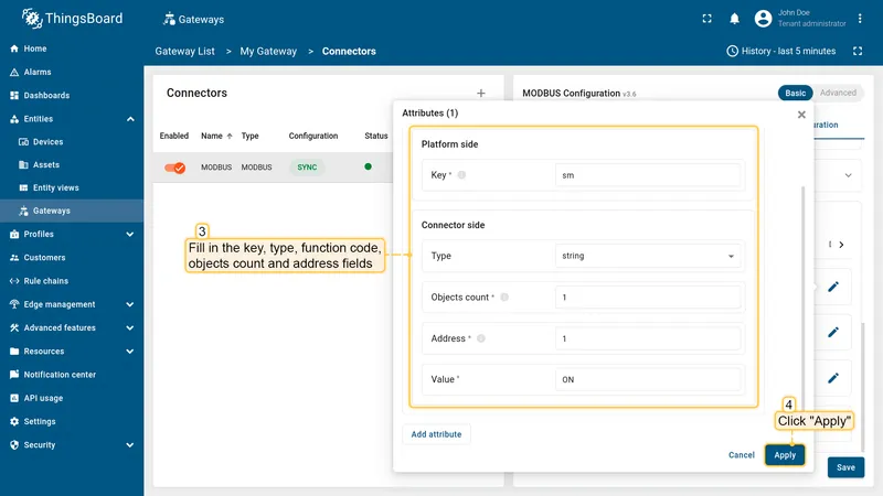
To add new value to the gateway slave, use the following steps:
-
Click on “pencil” icon in the row of the selected section;
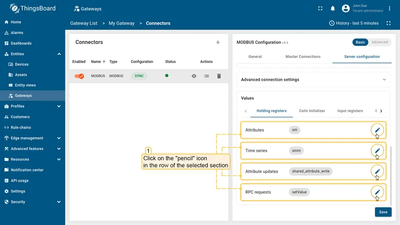
-
In the opened window click “Add attribute” or other (depends on selected section);

-
Fill in key, type, function code, objects count, address and value fields. Click “Apply”.


Advanced configuration
Section titled “Advanced configuration”The advanced configuration section provides a detailed overview of all available parameters for the Gateway as a Slave configuration section.
Gateway can run as a Modbus slave. This configuration section for the Modbus slave, which is used to store data and send updates to the platform when changes occur or at fixed intervals.
| Parameter | Default value | Description |
|---|---|---|
| slave.byteOrder | LITTLE | The order of bytes to read. |
| slave.wordOrder | LITTLE | The order of words when reading several registers. |
| slave.pollPeriod (in ms) | 5000 | Period in milliseconds to read and send the attributes and the telemetry to the platform. |
| slave.sendDataToThingsBoard | true | If set to TRUE, the Gateway will perform autoconfiguration and send values to ThingsBoard every poll period |
| slave.unitId | ID of current gateway slave on Modbus. | |
| slave.deviceName | Device name on the platform. | |
| slave.deviceType | default | (Optional) Device profile name on the platform. |
Example of the slave configuration:
"slave": { "type": "tcp", "host": "127.0.0.1", "port": 5026, "method": "socket", "deviceName": "Modbus Slave Example", "deviceType": "default", "pollPeriod": 5000, "sendDataToThingsBoard": false, "byteOrder": "LITTLE", "wordOrder": "LITTLE", "unitId": 0, ...}Slave connection types
Section titled “Slave connection types”The Modbus connector supports three types of connections to the Modbus slave:
- TCP - connection to the Modbus slave over TCP/IP protocol.
- UDP - connection to the Modbus slave over UDP protocol.
- Serial - connection to the Modbus slave over serial port (RS-232, RS-485, etc.).
TCP/UDP
Section titled “TCP/UDP”| Parameter | Description |
|---|---|
| slave.type | Type of connection to Modbus device, can be: tpc or udp. |
| slave.host | Hostname or ip address of Modbus server. |
| slave.port | Port of Modbus server for connection. |
| slave.method | Type of a framer Socket or RTU, if needed. |
Example of the TPC/UDP configuration:
"slave": { "type": "tcp", "host": "127.0.0.1", "port": 5026, "method": "socket", ...}Serial
Section titled “Serial”| Parameter | Default value | Description |
|---|---|---|
| slave.type | serial | Type of connection to Modbus device, can be: tpc or udp. |
| slave.port | Port of Modbus slave for connection. | |
| slave.method | rtu | Type of a framer Socket or RTU, if needed. |
| slave.baudrate | 19200 | (Optional) Baud rate for serial connection. |
| slave.stopbits | 1 | (Optional) The number of bits sent after each character in a message to indicate the end of the byte. |
| slave.parity | N | (Optional) The type of checksum to use to verify data integrity. This can be on of the following: (E) ven, (O)dd, (N)one. |
| slave.bytesize | 8 | (Optional) The number of bits in a byte of serial data. This can be one of 5, 6, 7, or 8. |
| slave.strict | true | (Optional) Use Inter char timeout for baud rates less than or equal to 19200. |
| slave.handleLocalEcho | false | (Optional) Handle local echo for serial connections. This is useful for devices that echo back the data sent to them. |
Example of the serial configuration:
"slave": { "type": "serial", "port": 5026, "method": "rtu", "baudrate": 4800, "stopbits": 1, "bytesize": 5, "parity": "N", "strict": true, "handleLocalEcho": false, ...}Security
Section titled “Security”The Gateway as a Salve supports security configuration. This configuration is used to secure the connection to the Modbus slave and to authenticate the connection. Available only for the TCP and UDP connections.
| Parameter | Description |
|---|---|
| slave.security | Security object. |
| slave.security.keyfile | Hostname or ip address of Modbus server. |
| slave.security.certfile | Port of Modbus server for connection. |
| slave.security.password | Type of a framer Socket or RTU, if needed. |
Example of the security configuration:
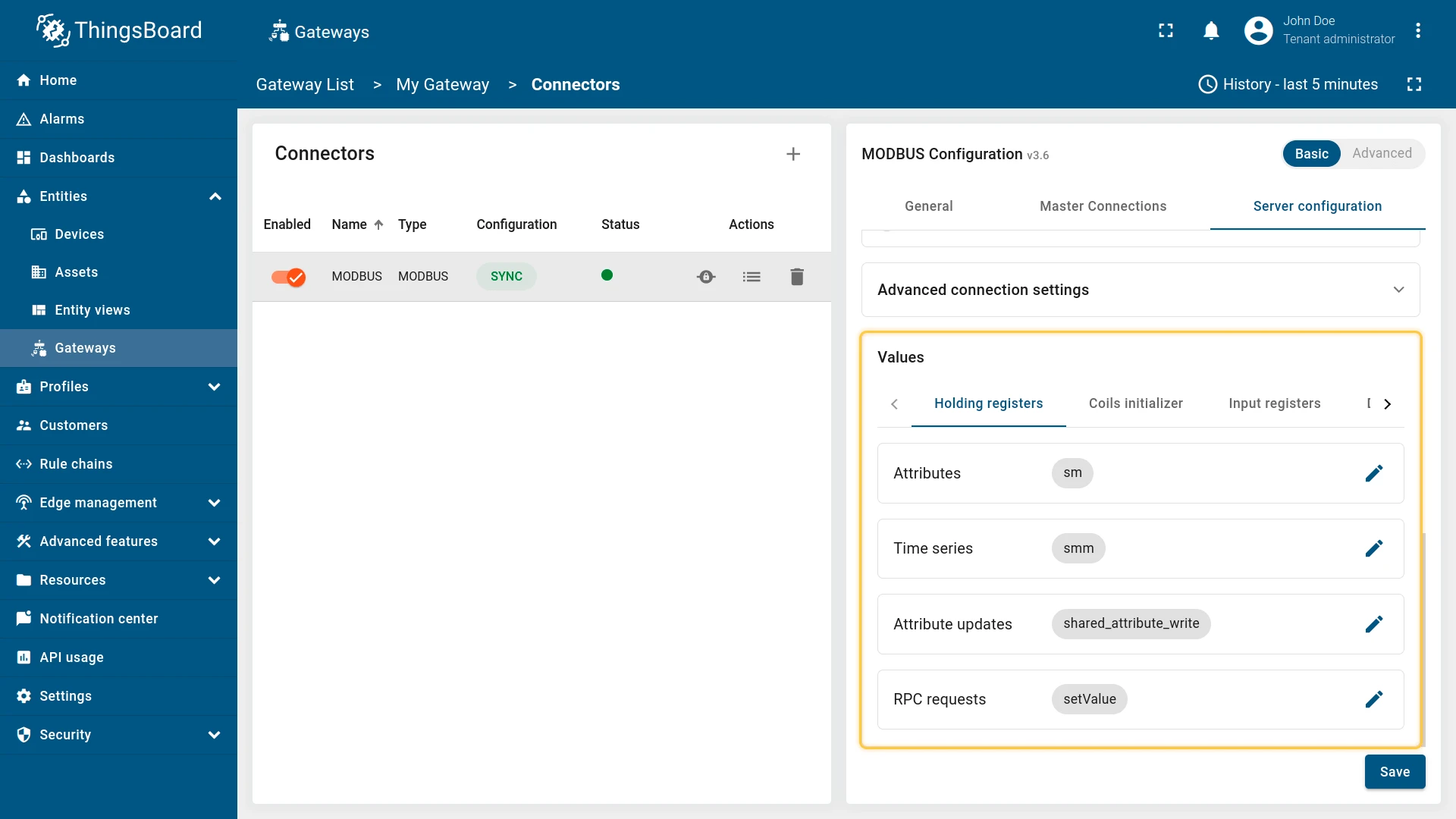
"slave": { "type": "tcp", "host": "127.0.0.1", "port": 5026, "method": "socket", "security": { "keyfile": "/path/to/keyfile.pem", "certfile": "/path/to/certfile.pem", "password": "your_password" } ...}Values
Section titled “Values”The Values list is used to specify the initial values for registers and coils. Each value refers to a specific type of register. There are:
- Holding registers
- Coils initializer
- Input registers
- Discrete inputs
For each register type, you can configure the value types that will be used to read/write data. According to the data type you select, the gateway will use the appropriate Modbus function code to read or write data.
Attributes and timeseries
Section titled “Attributes and timeseries”| Parameter | Description |
|---|---|
slave.values[].<register_type>.attributes[] | The list of attributes. |
slave.values[].<register_type>.attributes[].tag | Key name of the attribute on the platform. |
slave.values[].<register_type>.attributes[].address | Object address. |
slave.values[].<register_type>.attributes[].type | Type of value. |
slave.values[].<register_type>.attributes[].objectsCount | Count of objects to write. |
slave.values[].<register_type>.attributes[].value | Initial register value. |
slave.values[].<register_type>.attributes[].bitTargetType | The response type can be either an integer (0/1) or a boolean (True/False). Used only with type bits. |
slave.values[].<register_type>.timeseries[] | The list of timeseries. |
slave.values[].<register_type>.timeseries[].tag | Key name of the timeseries on the platform. |
slave.values[].<register_type>.timeseries[].address | Object address. |
slave.values[].<register_type>.timeseries[].type | Type of value. |
slave.values[].<register_type>.timeseries[].objectsCount | Count of objects to write. |
slave.values[].<register_type>.timeseries[].value | Initial register value. |
slave.values[].<register_type>.timeseries[].bitTargetType | The response type can be either an integer (0/1) or a boolean (True/False). Used only with type bits. |
Example of the attributes and timeseries configuration:
"slave": { ... "values": { "holding_registers": { "attributes": [ { "address": 1, "type": "string", "tag": "sm", "objectsCount": 1, "value": "ON" } ], "timeseries": [ { "address": 2, "type": "16int", "tag": "smm", "objectsCount": 1, "value": 12334 } ], } }}Attribute updates
Section titled “Attribute updates”| Parameter | Description |
|---|---|
slave.values[].<register_type>.attributeUpdates[] | The list of attribute updates. |
slave.values[].<register_type>.attributeUpdates[].tag | Key name of the attribute on the platform. |
slave.values[].<register_type>.attributeUpdates[].address | Object address. |
slave.values[].<register_type>.attributeUpdates[].type | Type of value. |
slave.values[].<register_type>.attributeUpdates[].functionCode | Function code to write value. |
slave.values[].<register_type>.attributeUpdates[].objectsCount | Count of objects to write. |
slave.values[].<register_type>.attributeUpdates[].value | Initial register value. |
slave.values[].<register_type>.attributeUpdates[].bitTargetType | The response type can be either an integer (0/1) or a boolean (True/False). Used only with type bits. |
Example of the attribute updates configuration:
"slave": { ... "values": { "holding_registers": { "attributeUpdates": [ { "tag": "shared_attribute_write", "type": "32int", "functionCode": 6, "objectsCount": 2, "address": 29, "value": 1243 } ], } }}RPC methods
Section titled “RPC methods”| Parameter | Description |
|---|---|
slave.values[].<register_type>.rpc[] | The list of attribute updates. |
slave.values[].<register_type>.rpc[].tag | Key name of the attribute on the platform. |
slave.values[].<register_type>.rpc[].address | Object address. |
slave.values[].<register_type>.rpc[].type | Type of value. |
slave.values[].<register_type>.rpc[].functionCode | Function code to write value. |
slave.values[].<register_type>.rpc[].objectsCount | Count of objects to write. |
slave.values[].<register_type>.rpc[].value | Initial register value. |
slave.values[].<register_type>.rpc[].bitTargetType | The response type can be either an integer (0/1) or a boolean (True/False). Used only with type bits. |
Example of the RPC methods configuration:
"slave": { ... "values": { "holding_registers": { "rpc": [ { "tag": "setValue", "type": "16int", "functionCode": 5, "objectsCount": 1, "address": 31, "value": 22 } ] } }}Additional information
Section titled “Additional information”Here’s more details regarding Modbus functions and the supported data types.
Modbus functions
Section titled “Modbus functions”The Modbus connector supports the following Modbus functions:
| Modbus function code | Description |
|---|---|
| Read data | |
| 1 | Read Coils |
| 2 | Read Discrete Inputs |
| 3 | Read Multiple Holding Registers |
| 4 | Read Input Registers |
| Write data: | |
| 5 | Write Coil |
| 6 | Write Register |
| 15 | Write Coils |
| 16 | Write Registers |
Data types
Section titled “Data types”A list and description of the supported data types for reading/writing data.
| Type | Function code | Objects count | Note |
|---|---|---|---|
| string | 3-4 | 1-… | Read bytes from registers and decode it (‘UTF-8’ coding). |
| bytes | 3-4 | 1-… | Read bytes from registers. |
| bits | 1-4 | 1-… | Read coils. If the objects count is 1, result will be interpreted as a boolean. Otherwise the result will be an array with bits. |
| 16int | 3-4 | 1 | Integer 16 bit. |
| 16uint | 3-4 | 1 | Unsigned integer 16 bit. |
| 16float | 3-4 | 1 | Float 16 bit. |
| 32int | 3-4 | 2 | Integer 32 bit. |
| 32uint | 3-4 | 2 | Unsigned integer 32 bit. |
| 32float | 3-4 | 2 | Float 32 bit. |
| 64int | 3-4 | 4 | Integer 64 bit. |
| 64uint | 3-4 | 4 | Unsigned integer 64 bit. |
| 64float | 3-4 | 4 | Float 64 bit. |
Was this helpful?