OPC-UA Integration
OPC-UA (Open Platform Communications Unified Architecture, IEC 62541) is a platform-independent industrial M2M protocol for reliable, secure data exchange in automation and IoT systems. The ThingsBoard OPC-UA Integration connects to an OPC-UA server, subscribes to the device nodes you configure, decodes their values with an uplink converter, and pushes the resulting telemetry and attributes into the platform. In the reverse direction it can encode Rule Engine messages with a downlink converter and deliver them to OPC-UA nodes as write operations or method calls.
When to use OPC-UA Integration:
- Your data lives on an OPC-UA server — a PLC, SCADA gateway, historian, or any other OPC-UA-capable device — and you want ThingsBoard to monitor it as telemetry and attributes.
- You need to both read node values and write back to the server (attribute writes or method calls), not just one-way ingestion.
- You want ThingsBoard to auto-discover and provision a device for every node matching a pattern, instead of registering devices one by one.
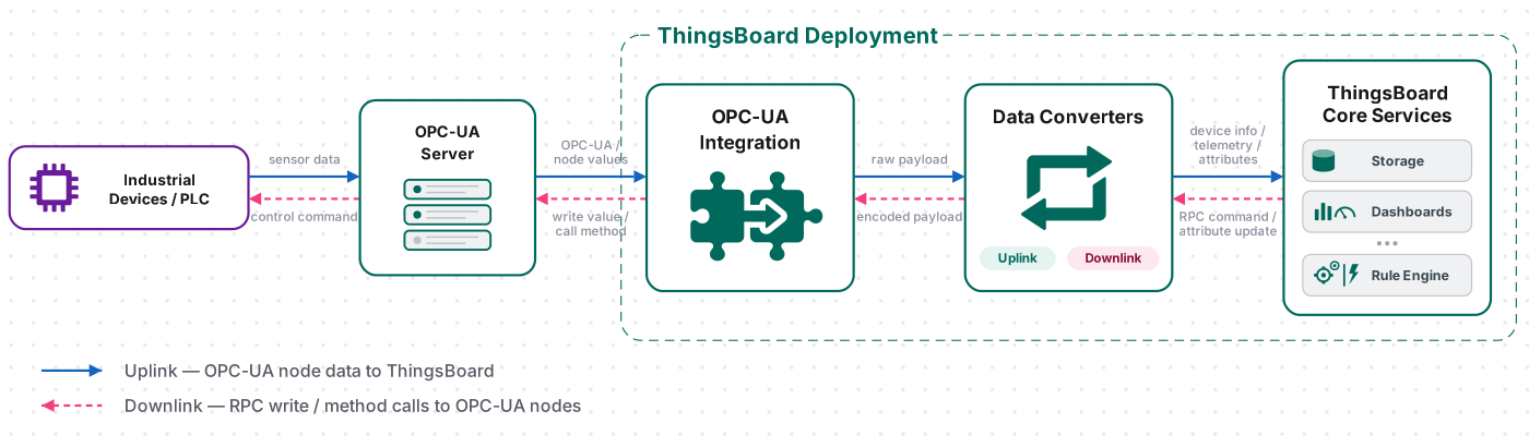
In this guide the OPC-UA server is the public Prosys OPC UA demo server (opc.tcp://uademo.prosysopc.com:53530/OPCUA/SimulationServer) — a free, internet-hosted instance of the Prosys OPC UA Simulation Server. It is always running, exposes a ready-to-use address space with continuously changing simulated values, and requires no installation, so you can follow the example on any operating system without setting up a server.
Prerequisites
Section titled “Prerequisites”- You have access to ThingsBoard Cloud with integration functionality enabled for your tenant.
- You have permissions to create integrations and data converters.
- Outbound network access from the integration to the public demo server: the machine running the integration (the ThingsBoard cluster, or a Remote Integration host) must be able to open a TCP connection to
uademo.prosysopc.comon port53530. If outbound traffic is restricted, run the integration as a Remote Integration from a host that has internet access. - The connection details are fixed for this demo — see Public Prosys OPC UA Demo Server below for the exact values.
Public Prosys OPC UA Demo Server
Section titled “Public Prosys OPC UA Demo Server”You do not install anything — the server is already running on the internet. Everything the integration needs is summarized here.
- Endpoint —
opc.tcp://uademo.prosysopc.com:53530/OPCUA/SimulationServer, which splits into Hostuademo.prosysopc.com, Port53530, and Endpoint path/OPCUA/SimulationServer. - Security —
Noneonly. The public server does not allowSignorSign&Encrypt; use a self-hosted server if you need a secure connection. - Authentication —
Anonymous; no username or password. - Simulation — always on. Values change continuously on the server side; there is nothing to start or stop.
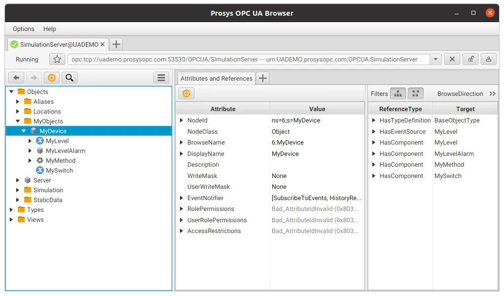
Example nodes. The server exposes the standard Prosys Simulation Server address space. This guide reads the sample device MyDevice:
- Full path (FQN):
Objects.MyObjects.MyDevice - MyLevel — a
Doublevariable holding a simulated level measurement that changes continuously (read as telemetry). - MyLevelAlarm — a
Booleanvariable that turns on when MyLevel crosses a threshold. - MyMethod — a callable sample method.
- MySwitch — a
Booleanvariable (read as an attribute).
The Simulation folder on the same server also contains additional ready-made changing signals that you can add later as extra subscription tags.
Set Up the OPC-UA Integration
Section titled “Set Up the OPC-UA Integration”To set up the OPC-UA integration, first create an uplink data converter to process incoming messages, then create and configure the integration.
Create the Uplink Data Converter
Section titled “Create the Uplink Data Converter”The uplink converter decodes the raw OPC-UA message and maps it to the ThingsBoard data model (device identity, telemetry, and attributes). It receives:
payload— a JSON object keyed by your subscription-tag Keys, e.g.{"level": "42.17", "switchState": "true"}(values arrive as strings).metadata— node metadata:opcUaNode_name,opcUaNode_namespaceIndex,opcUaNode_identifier,opcUaNode_fqn, andintegrationName.
Sample input
{ "payload": { "level": "42.17", "switchState": "true" }, "metadata": { "opcUaNode_name": "MyDevice", "opcUaNode_namespaceIndex": "6", "opcUaNode_identifier": "MyDevice", "opcUaNode_fqn": "Objects.MyObjects.MyDevice", "integrationName": "OPC-UA integration" }}Create the converter
The quickest path is inline in the integration wizard: on the Uplink data converter step (covered in Create OPC-UA Integration below), keep Create new and paste the decoder below into the Main decoding configuration editor, leaving the language toggle on TBEL. To create it as a reusable converter instead:
- Go to Integrations ⇾ Data converters and click + Add data converter ⇾ Create new converter.
- Set Converter type to Uplink.
- Enter a name, e.g.
OPC-UA Uplink Converter. - Paste the decoder function below into the editor.
- Optionally click Test decoder function with the sample input above to validate, then click Add. Select it later on the wizard’s Uplink step via Select existing.
// OPC-UA default uplink converter (TBEL)// Decodes incoming OPC-UA node values and maps them to the ThingsBoard data model.
// Parse the incoming payload (JSON with node values) into an object.var data = decodeToJson(payload);
// Resolve the device name from node metadata.// Coerce to string (the value may be numeric, e.g. 111).// Fall back to a default name when 'opcUaNode_name' is missing.var nodeName = metadata['opcUaNode_name'];var deviceName = nodeName != null ? nodeName + '' : 'OPC-UA Device';var deviceType = 'opc-ua-device';
// Build the result message. Node identifiers are stored as attributes// so they don't pollute telemetry.var result = {  deviceName: deviceName,  deviceType: deviceType,  attributes: {    nodeFqn: metadata['opcUaNode_fqn'],    namespaceIndex: metadata['opcUaNode_namespaceIndex'],    identifier: metadata['opcUaNode_identifier']  },  telemetry: {}};
// Map every subscription tag from the payload into telemetry.// Numeric strings are converted to numbers; everything else is kept as-is.foreach (key : data.keySet()) {  var value = data[key];  if (value != null) {    // Match integers, decimals, negatives and scientific notation (e.g. 1.5e-3).    if (value instanceof String && value.matches("[-+]?\\d*\\.?\\d+([eE][-+]?\\d+)?")) {    result.telemetry[key] = parseDouble(value);  } else {    result.telemetry[key] = value;  }}}
// Helper functions 'decodeToString' and 'decodeToJson' are built into TBEL.
return result;// OPC-UA default uplink converter (JavaScript)// Decodes incoming OPC-UA node values and maps them to the ThingsBoard data model.
// Parse the incoming payload (JSON with node values) into an object.var data = decodeToJson(payload);
// Resolve the device name from node metadata.// Coerce to string (the value may be numeric, e.g. 111).// Fall back to a default name when 'opcUaNode_name' is missing.var nodeName = metadata['opcUaNode_name'];var deviceName = nodeName != null ? nodeName + '' : 'OPC-UA Device';var deviceType = 'opc-ua-device';
// Build the result message. Node identifiers are stored as attributes// so they don't pollute telemetry.var result = { deviceName: deviceName, deviceType: deviceType, attributes: { nodeFqn: metadata['opcUaNode_fqn'], namespaceIndex: metadata['opcUaNode_namespaceIndex'], identifier: metadata['opcUaNode_identifier'] }, telemetry: {}};
// Map every subscription tag from the payload into telemetry.// Numeric strings are converted to numbers; everything else is kept as-is.for (var key in data) { if (data.hasOwnProperty(key)) { var value = data[key]; if (value === null || value === undefined) { continue; } var num = Number(value); // Convert only real numeric values; leave booleans and empty strings untouched. if (typeof value !== 'boolean' && value !== '' && !isNaN(num)) { result.telemetry[key] = num; } else { result.telemetry[key] = value; } }}
// Helper functions to decode a raw byte payload into a JSON object.function decodeToString(payload) { return String.fromCharCode.apply(String, payload);}
function decodeToJson(payload) { var str = decodeToString(payload); return JSON.parse(str);}
return result;Expected ThingsBoard output
{ "deviceName": "MyDevice", "deviceType": "opc-ua-device", "telemetry": { "level": 42.17 }, "attributes": { "namespaceIndex": "3", "nodeFqn": "Objects.MyObjects.MyDevice", "switchState": true }}Adapt the converter: to read different or additional nodes, add matching subscription tags in the mapping (each new Key appears as a field in payload) and add a corresponding if (data.<key> != null) block that assigns it to telemetry or attributes. Change deviceType to whatever profile you want, or derive deviceName from metadata['opcUaNode_fqn'] when a single folder holds many devices. For the full function reference see Uplink data converter.
Create the OPC-UA Integration
Section titled “Create the OPC-UA Integration”- Go to Integrations ⇾ Integrations and click + Add integration.
- Basic settings:
- Set Integration type to OPC-UA.
- Enter a Name for the integration, or keep the default name,
OPC-UA integration. - Leave Enable integration and Allow create devices or assets enabled so that devices are created automatically when data is received for the first time.
- Click Next.
- Uplink data converter:
- Click Select existing and choose the OPC-UA Uplink Converter created in the previous step. Alternatively, click Create new to create the converter directly in the wizard.
- Click Next.
- Downlink data converter:
- Click Skip. A downlink converter is required only when ThingsBoard must send data back to the device, for example, through RPC commands or shared attribute updates. You can configure it later.
- Configure the OPC-UA server connection:
On the Connection step, map the public demo server endpoint (
opc.tcp://uademo.prosysopc.com:53530/OPCUA/SimulationServer) to the following fields:- Host —
uademo.prosysopc.com. - Port — the field is pre-filled with
49320. Change it to53530. - Endpoint — enter
/OPCUA/SimulationServer, including the leading slash. - Security — select
None. The public demo server accepts unsecured connections only. - Identity — select
Anonymous. The demo server does not provide user accounts.
- Host —
- Configure node mapping:
The mapping determines which nodes represent devices and which child node values ThingsBoard reads from each device node. ThingsBoard browses the server address space, identifies nodes that match the configured pattern, and subscribes to the child nodes specified as subscription tags.
Configure the following settings in the Mapping section:
Mapping type — select
Fully Qualified Name. With this option, nodes are matched by their full browse path, for example,Objects.MyObjects.MyDevice. To match nodes by namespace index and node identifier instead, selectID. An additional Namespace field then appears.Device Node Pattern — enter a regular expression that selects the nodes representing devices. The pattern is applied to the node paths or node IDs, depending on the selected mapping type. The field is pre-filled with the example
Channel1\.Device\d+$. Replace it with the pattern that matches the Prosys demo server node:
Only nodes that match this expression are selected.Objects\.MyObjects\.MyDevice$Subscription tags — define the child node values to read from each matched device node. Each tag contains a Key, which becomes the field name in the message payload, and a Path, which identifies the child node relative to the device node.
Key Path Description levelMyLevelSimulated level measurement ( Double)switchStateMySwitchSimulated switch state ( Boolean)Select Required only if the entire message must be rejected when the corresponding value is unavailable. Click Add subscription tag to add each value. Click Add mapping element to configure another device group that uses a different node pattern.
- Click Add to finish creating the integration.
Connection Settings
Section titled “Connection Settings”Host
Hostname or IP address of the OPC-UA server.
Port
Port number of the OPC-UA server. Default: 49320.
Endpoint
Optional path suffix appended to the server address when constructing the OPC-UA connection URL. Use this when the server exposes a specific endpoint path, for example /OPCUA/SimulationServer. Leave blank if the server listens on the root path (most common for demo servers).
Security
Message security policy for the OPC-UA session. Default: None.
None— no encryption or signing (suitable for local/trusted networks)Basic128Rsa15— 128-bit symmetric encryption, RSA-15 key exchangeBasic256— 256-bit symmetric encryptionBasic256Sha256— 256-bit symmetric encryption with SHA-256 signing (recommended for production)
When any policy other than None is selected, additional fields appear for the client keystore ThingsBoard uses to authenticate itself to the server:
- Type — keystore format:
JKSorPKCS12 - Location — Browse file to upload the keystore directly, or Use Secret storage to reference a keystore already stored in Secrets storage
- Alias — alias of the key entry inside the keystore
- Password — password protecting the keystore
- Key password — password protecting the private key entry identified by Alias
Identity
Authentication method used when establishing the OPC-UA session:
Anonymous— no credentials required; the server must have anonymous logon enabledUsername— additional Username and Password fields appear; authenticate with a server-side account
Mapping Type
Determines how ThingsBoard identifies device nodes on the OPC-UA server:
Fully Qualified Name— matches nodes by their full browsed path (e.g.Objects.BuildingAutomation.AirConditioner_1)ID— matches nodes by namespace index and node identifier
Device Node Pattern
Regular expression applied to OPC-UA node names or IDs to identify which nodes represent devices. Only nodes matching this pattern are subscribed to. Example: Channel1\.Device\d+$.
Mapping type, Device Node Pattern, Namespace, and Subscription tags together form one mapping element. Click Add mapping element to define another, differently-patterned device group — for example, to subscribe to two device types under different node paths.
Namespace
OPC-UA namespace index used to scope node identifiers. Only visible when Mapping type is set to ID.
Subscription Tags
Defines which child node values ThingsBoard reads from each matched device node. Each entry has:
- Key — the field name used in the ThingsBoard message payload (e.g.
temperature) - Path — relative path of the child node under the matched device node (e.g.
Temperature) - Required — when checked, a missing or unreadable value for this tag prevents the message from being processed; leave unchecked for optional tags
Click Add subscription tag to read additional child values from the same device node; use the × control next to a tag to remove it.
Execute Remotely
When enabled, ThingsBoard generates an Integration key and Integration secret that allow the integration to run as a separate Remote Integration process outside the ThingsBoard cluster. This is the recommended approach when the OPC-UA server is only reachable from a local or isolated network that has no direct path to ThingsBoard.
Advanced Settings
- Application name — OPC-UA client application name sent to the server during session establishment (informational)
- Application uri — OPC-UA client application URI; must be globally unique per the OPC-UA specification
- Scan period in seconds — how frequently ThingsBoard re-browses the server’s node hierarchy to discover newly added or removed devices and subscription tags. It does not control how often telemetry values update — see Data acquisition model below. Default:
10 - Timeout in milliseconds — connection and request timeout. Default:
5000 - Description — optional text description for the integration
- Metadata — key-value pairs injected into every uplink message as
integrationMetadatain converter scripts
Test Uplink
Section titled “Test Uplink”Verify OPC UA Server Data
Section titled “Verify OPC UA Server Data”No server action is needed — the public demo server is always running and MyLevel is always changing.
Verify Integration Events
Section titled “Verify Integration Events”Open the integration and check its Events tab. Successful Uplink events with Status OK confirm the integration connected and is receiving pushed value changes from the subscribed nodes; error events show the reason a connection or decode failed.
Verify Converter Events
Section titled “Verify Converter Events”To inspect converter processing, go to Integrations ⇾ Data converters, click OPC-UA Uplink Converter, and open its Events tab. Each row adds In, Out, and Metadata columns — click the ⋯ icon in any of them to open its JSON in a dialog.
- In — the raw payload passed to the converter, keyed by your subscription tag names
- Out — the decoded result returned to ThingsBoard
- Metadata — the integration and node metadata
Verify Device Provisioning
Section titled “Verify Device Provisioning”For each matched node, the integration builds a message and hands it to the uplink converter. The converter returns a deviceName and deviceType; ThingsBoard creates a device with that name/type on first data (because Allow create devices is on) or matches an existing one.
Go to Devices & assets ⇾ Devices, find the device named MyDevice (type opc-ua-device). Open it and check:
- Latest telemetry — a
levelvalue that refreshes as the demo server reports changes (about once per second, per the fixed subscription interval described in Data acquisition model above). - Attributes (Client attributes scope) —
namespaceIndex,identifier,nodeFqn.
Configure Downlink
Section titled “Configure Downlink”Downlink lets ThingsBoard write back to the server. The Rule Engine turns an RPC (or shared-attribute update) into a message, routes it through an Integration Downlink rule node to the downlink converter, and the converter encodes it into OPC-UA write operations or method calls.
The encoder must return an object with:
contentType—JSON.data— a JSON string with two optional arrays:writeValues—{nodeId, value}pairs. NodeId format:ns=<namespaceIndex>;<type>=<identifier>, where<type>iss(string),i(numeric),g(GUID), orb(byte string).callMethods—{objectId, methodId, args}objects.
metadata— must be an empty object{}for OPC-UA.
The converter below reacts to an RPC named setSwitch carrying a boolean parameter and writes it to the device’s MySwitch node.
Read the exact NodeId of MySwitch using the same Prosys OPC UA Browser you used earlier to browse the address space, rather than assuming a namespace index.
For a method call instead of a write (e.g. MyMethod), leave writeValues empty and push to callMethods using the same shape described above, reading both NodeIds from the server. For the complete encoder reference and testing tools see Downlink data converter.
Create and Assign the Downlink Converter
Section titled “Create and Assign the Downlink Converter”- Go to Integrations ⇾ Integrations and open the OPC-UA integration.
- Click the pencil icon to enter edit mode.
- In the Downlink data converter field, click Create new.
- In the Add data converter dialog:
- Enter a name for the converter, for example,
OPC-UA Downlink Converter. - Use the default encoder script or replace it with your own implementation.
- Click Add.
- Enter a name for the converter, for example,
- Click Apply changes to save the integration.
The encoder function used in this tutorial:
// Trigger example: { "method": "setSwitch", "params": true }var data = {  writeValues: [],  callMethods: []};
if (msgType == 'RPC_CALL_FROM_SERVER_TO_DEVICE' && msg.method == 'setSwitch') {  // cs_namespaceIndex is the client attribute 'namespaceIndex' pulled into metadata  // by the 'originator attributes' rule node (cs_ = client-scope prefix).  var nodeId = 'ns=' + metadata['cs_namespaceIndex'] + ';s=MySwitch';
  // Normalize the RPC parameter to a real Boolean  var value = (msg.params == true || msg.params == 'true' || msg.params == 1 || msg.params == '1');
  data.writeValues.push({ nodeId: nodeId, value: value });}
var result = {  contentType: 'JSON',  data: JSON.stringify(data),  metadata: {}};
return result;
// Trigger example: { "method": "setSwitch", "params": true }var data = { writeValues: [], callMethods: []};
if (msgType === 'RPC_CALL_FROM_SERVER_TO_DEVICE' && msg.method === 'setSwitch') { // cs_namespaceIndex = client attribute 'namespaceIndex' added to metadata by the // 'originator attributes' node. var nodeId = 'ns=' + metadata['cs_namespaceIndex'] + ';s=MySwitch'; var value = (msg.params === true || msg.params === 'true' || msg.params === 1 || msg.params === '1');
data.writeValues.push({ nodeId: nodeId, value: value });}
var result = { contentType: 'JSON', data: JSON.stringify(data), metadata: {}};
return result;Configure the Root Rule Chain
Section titled “Configure the Root Rule Chain”Two rule nodes route RPC requests to the OPC-UA integration: an originator attributes node that reads the device’s namespaceIndex client attribute and injects it into message metadata (the downlink converter reads it as cs_namespaceIndex to build the NodeId), and an integration downlink node that sends the message to the integration.
- Go to Data processing ⇾ Rule chains ⇾ Root Rule Chain.
- In the Enrichment section of the node library, find the originator attributes node and drag it onto the canvas.
- Configure the node:
- Name — e.g.
Retrieve namespaceIndex. - Under Client attributes, add
namespaceIndex. - Set Add originator attributes to to Metadata.
- Click Add.
- Name — e.g.
- In the node panel, search for integration downlink and drag it onto the canvas.
- Configure the node:
- Name — e.g.
Downlink to OPC-UA. - Under Integration — select OPC-UA integration.
- Click Add.
- Name — e.g.
- Connect the message type switch node to the originator attributes node using the RPC Request to Device relation.
- Connect the originator attributes node to the integration downlink node using the Success relation.
- Click Apply changes.
Test Downlink
Section titled “Test Downlink”Send the RPC. Trigger a one-way RPC to the MyDevice device, for example via the REST API:
curl -X POST "https://<your-thingsboard-host>/api/rpc/oneway/<DEVICE_ID>" \-H "Content-Type: application/json" \-H "X-Authorization: Bearer <JWT_TOKEN>" \-d '{"method":"setSwitch","params":true}'Verify Downlink Converter Events
Section titled “Verify Downlink Converter Events”Go to Integrations ⇾ Data converters, open OPC-UA Downlink Converter, and click the Events tab. Click an event row to inspect:
- In — the Rule Engine message received by the converter:
msgcontains the RPCmethodandparams;metadata.cs_namespaceIndexandmetadata.deviceNameare injected by the originator attributes node. - Out — the encoded output sent to the integration: a JSON
writeValuesarray with your NodeId and value.
Verify the Write on the OPC UA Server
Section titled “Verify the Write on the OPC UA Server”In the Prosys OPC UA Browser, select MySwitch and confirm its value flipped to what you sent.
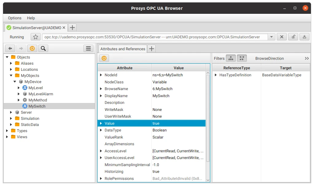
Expected result: the RPC reaches the integration, the downlink converter emits a writeValues entry, and MySwitch on the server changes to the sent boolean. If you also added a switchState → MySwitch subscription tag, the new value flows back into ThingsBoard as an attribute as soon as the server reports the change.
Troubleshooting
Section titled “Troubleshooting”| Symptom | Cause | Fix |
|---|---|---|
| Connection refused / timeout | No outbound internet from the integration host, or a firewall blocking port 53530 |
Verify the integration host can reach uademo.prosysopc.com:53530 (e.g. telnet/nc); allow outbound TCP 53530; if the ThingsBoard cluster has no internet, enable Execute remotely and run from a host that does. |
| Incorrect endpoint URL | Missing or wrong Endpoint path | Set Host = uademo.prosysopc.com, Port = 53530, Endpoint = /OPCUA/SimulationServer (exact, with leading slash). |
| Incompatible security policy / message security mode | A secure mode was selected | The public demo accepts None only — set Security = None. For Sign/Sign&Encrypt, run your own Prosys server. |
| Discovery / endpoint hostname error | The demo server may return an endpoint without a fully qualified domain name | Re-try the connection; keep Security = None; if it persists, run a local Prosys server and connect to opc.tcp://localhost:53530/OPCUA/SimulationServer instead. |
| Authentication failure | An identity other than Anonymous was selected | Set Identity = Anonymous; the public server has no user accounts. |
| Nodes not found / no matching devices | Device Node Pattern does not match any node path | Browse the address space with the Prosys OPC UA Browser; escape dots in the regex (Objects\.MyObjects\.MyDevice$); confirm Mapping type matches how the pattern is written (FQN vs ID). |
| Device not created | No successful uplink yet, or Allow create devices disabled | Check the integration Events tab for errors; enable Allow create devices; confirm the converter returns a non-empty deviceName. |
| Integration receives data but telemetry is missing | Payload keys don’t match the converter, or values not assigned to telemetry |
Ensure subscription-tag Keys match the data.<key> names in the converter; confirm values are placed under telemetry (attributes go under attributes). |
| Values do not update | Subscription dropped, or the underlying value genuinely isn’t changing on the server | Check the Events tab for reconnects/errors; confirm the node is still being matched and subscribed to. Scan period only affects discovery of new/removed nodes, not value refresh — the demo server itself updates values continuously. |
See Also
Section titled “See Also”- Integrations Overview — how ThingsBoard connects to external platforms and how uplink/downlink flow works
- Uplink Data Converter — full decoder function reference: input parameters, output fields, and scripting patterns
- Downlink Data Converter — full encoder function reference for sending commands to devices
- Remote Integration — run the integration outside the ThingsBoard server to reach OPC-UA servers in a private network
- TBEL Scripting Reference — built-in functions and operators for writing converter scripts
- Rule Engine — how uplink messages are processed after the converter
- Secrets Storage — upload and manage the keystores referenced by the Security connection settings
- Monitor and Control Airconditioners over OPC-UA — stream airconditioner telemetry from an OPC-UA server to a live dashboard, then turn devices on or off via downlink and a rule chain
Was this helpful?